Taking Advantage of New Air Brake Features in Open Rails 1.6

Collapse
This is a sticky topic.
X
X
 
  • Time
  • Show
Clear All
new posts
  • pschlik
    Senior Member


    • Jun 2011
    • 289
    • Missouri
    • MSOR

    #1

    Taking Advantage of New Air Brake Features in Open Rails 1.6

    Open Rails 1.6 brings a bunch of new air brake features that can more faithfully represent a variety of braking systems. Most of these were implemented back in 2023 so I've had plenty of time to research and fine tune the use of these features, so I can offer some effective examples for those who don't want to look at the manual.

    Relay Valves
    Many modern braking systems require large volumes of air or air at unusual pressures which the control valve/distributor cannot produce on its own. In this case, a relay valve is used so that a small supply of air at one pressure can control a much larger supply of air at an arbitrary pressure (much like how an electrical relay can take a 5 volt input signal to control a 500 volt output). One practical consequence of this is that you can multiply or divide brake cylinder pressure. However, this does create the added factor of needing to consider the pressure out of the control valve vs the pressure of the loco brake system vs the actual pressure sent to the brake cylinders. All 3 can be different now, and that's reality.

    For example, modern American locomotives have a relay valve that sends air at a 1:1 pressure ratio to the brake cylinders for train brake applications (from the control valve) but at a 1.6:1 pressure ratio for locomotive brake applications (from the independent application and release pipe). A relay valve is used as the volume of brake cylinders on a locomotive is far too big for a regular auxiliary reservoir to supply. The relay valve allows a tiny auxiliary res to 'calculate' the pressure we want, then use the huge main reservoir to actually provide that pressure. Thus, the only limit on brake performance is the pressure setting of the main reservoir.

    Code:
    Wagon ( Comment ( ALL relay valve parameters go in the WAGON section. J1.6-16 style locomotive relay valve. )
        ORTSBrakeRelayValveRatio ( 1.0 ) Comment ( The output/input pressure ratio for train brake applications, works on both wagons and engines. )
        ORTSEngineBrakeRelayValveRatio ( 1.6 ) Comment ( The output/input pressure ratio for locomotive brake applications, does nothing on wagons. )
        ORTSBrakeRelayValveApplicationRate ( 24psi/s ) Comment ( How quickly the brake cylinder pressure can increase. Will increase slower than this if the input pressure increases slowly. )
        ORTSBrakeRelayValveReleaseRate ( 32psi/s ) Comment ( How quickly the brake cylinder pressure can decrease. Will decrease slower than this if the input pressure decreases slowly.)
    )
    Side note; American locomotives use pressures in the range of 0-45 psi for the locomotive brake. Multiplying this by 1.6 produces a range 0-72 psi in the brake cylinders. If a locomotive works best with a different brake cylinder pressure, it simply uses a different relay valve ratio on the same 0-45 psi pressure. This way the system is cross-compatible without causing any one locomotive to provide too much or too little locomotive brake force.

    Code:
    Engine ( Comment ( Engine brake control goes in the ENGINE section. Valid for all AAR style locomotives. )
       EngineBrakesControllerMaxSystemPressure ( 45psi )
        EngineBrakesControllerFullServicePressureDrop ( 0psi )
        EngineBrakesControllerMinPressureReduction ( 0psi )
    )
    Another consideration is that many real relay valves (particularly the step-down types) add additional pressure at the low end to prevent unusually low output pressures sent to the brake cylinders. For example, if we have a step-down relay valve with a ratio of 0.5, an input pressure of 10 psi would lead to 5 psi sent to the brake cylinders. For some brake cylinders, 5 psi is so low it won't even extend the piston, so the valve can be modified to add on, say, 10 psi extra, giving an output of 15 psi. This addition of a bit of extra pressure is called inshot. In OR, this is incorporated with ORTSBrakeRelayValveInshot for train brakes and ORTSEngineBrakeRelayValveInshot for locomotive brakes, alongside the other relay valve parameters.

    There are two types of inshot. One type adds to the pressure output to the brake cylinder pressure directly, which is set by giving ORTSBrakeRelayValveInshot a positive pressure. The other type sets a minimum limit on the pressure output, which is set by giving ORTSBrakeRelayValveInshot a negative pressure.

    Observe this plot to see the difference between a negative, positive, and no inshot setting:
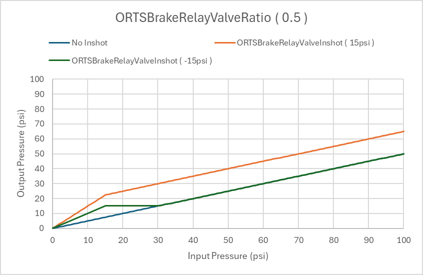


    Note how the positive inshot (orange line) provides a pressure that is always higher than the default behavior (blue line). Meanwhile, "negative inshot" (green line) provides a pressure that is only higher than the default behavior (blue line) at low pressures only. Both types exist in reality, and which is used on your engine/wagon depends entirely on how it functions in real life. Though note that "negative inshot" has no effect on relay valves with a ratio 1.0 or higher.

    I know for a fact that AAR empty/load brakes on freight cars follow the behavior of "negative" inshot where there is that plateau in output pressure as input pressure increases.
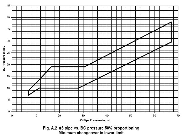
    Code:
    Wagon ( Comment ( AAR style 50% empty/load brake equipment. )
        ORTSBrakeRelayValveRatio ( 0.5 )
        ORTSBrakeRelayValveInshot ( -15psi ) Comment ( Still gives 32 psi brake cylinder pressure from a 64 psi train brake application, but initial 15 psi builds up more quickly. )
        ORTSBrakeRelayValveApplicationRate ( 10psi/s )
        ORTSBrakeRelayValveReleaseRate ( 10psi/s )
    )
    But some step-down locomotive relay valves are more accurately modeled by "positive" inshot. Note that inshot can be different for the train brake portion than for the locomotive brake portion.
    Code:
    Wagon ( Comment ( J64B style locomotive relay valve. )
        ORTSBrakeRelayValveRatio ( 0.4 )
        ORTSBrakeRelayValveInshot ( 6psi ) Comment ( From a 64 psi train brake application, gives 32 psi brake cylinder pressure. 64 * 0.4 + 6 = 31.6 )
        ORTSEngineBrakeRelayValveRatio ( 0.6 )
        ORTSEngineBrakeRelayValveInshot ( 5psi ) Comment ( From a 45 psi locomotive brake application, gives 32 psi brake cylinder pressure. 45 * 0.6 + 5 = 32 )
        
        ORTSBrakeRelayValveApplicationRate ( 12psi/s )
        ORTSBrakeRelayValveReleaseRate ( 16psi/s )
    )
    Another note: Some equipment has pressure limiting devices, but because the relay valve can disconnect the brake cylinder pressure from other pressures in the system the pressure limiting behavior is a bit different. It is now possible to set a pressure limit for the output from the control valve separately from the pressure limit on the brake cylinders. Correct settings depend on the equipment in question.
    Code:
    Wagon ( Comment ( Example settings only, not based on a real brake system. )
        ORTSMaxTripleValveCylinderPressure ( 64psi ) Comment ( This sets the maximum input pressure produced by the train brakes. )
        BrakeCylinderPressureForMaxBrakeBrakeForce ( 80psi ) Comment ( This sets the maximum output pressure that will ever be sent to the brake cylinders. )
    )
    And that's all for relay valves. This is probably the most important air brake feature added with 1.6, and you'll either know exactly where you've wanted to use it for years or will have no idea how any of this fits in.

    Supply Reservoirs
    As a companion to relay valves, supply reservoirs were also added in 1.6. Think of a supply reservoir as a main reservoir that can be attached to any rail vehicle, not just engines with a compressor. Unlike the auxiliary and emergency reservoirs, the supply reservoir is set up to always stay at a high pressure, regardless of brake applications, to provide air for various systems. The most relevant use of a supply reservoir in OR is to provide pressure to the brake cylinders on engines/wagons with excessively large or excessively many brake cylinders where the volume of air in the auxiliary reservoir would be too low to sufficiently pressurize the brake cylinders. (Supply reservoirs can be substantially larger than auxiliary reservoirs.)

    When combined with a relay valve, the air for the brake cylinders will be drawn from the supply reservoir instead of the auxiliary reservoir (the air in the auxiliary reservoir is instead sent to a dummy volume that does nothing but ensure the correct pressure results). The amount of air used depends on the size of the brake cylinders (more on that later). In turn, the supply reservoir is constantly recharged from the main res pipe or the brake pipe, making it very difficult to run out of air.

    The exact use of supply reservoirs will depend on the rolling stock in question, see your spec sheets and drawings, but one 'standard' example is freight cars with 8 axles, where the auxiliary reservoir supplies the brake cylinder pressure for 4 axles, and a 1:1 relay valve plus a supply reservoir with volume equal to the auxiliary res + emergency res (note the second air tank) supplies the brake cylinder pressure for the other 4 axles.

    Code:
    Wagon ( Comment ( Reservoir and relay valve settings for standardized 8 axle freight car. )
        BrakeSystemType ( "Air_single_pipe" )
        BrakeEquipmentType ( "Handbrake, Triple_valve, Auxiliary_reservoir, Emergency_brake_reservoir, Supply_reservoir, Retainer_3_Position" ) Comment ( Add "Supply_reservoir" to get a supply reservoir on your train. )
    
        EmergencyResCapacity ( 3500in^3 ) Comment ( Standard size emergency reservoir. )
        EmergencyResVolumeMultiplier ( 1.4 )
        
        MaxAuxilaryChargingRate ( 1.05psi/s )
        EmergencyResChargingRate ( 1.0psi/s )​
    
        ORTSSupplyResCapacity ( 6000in^3 ) Comment ( Supply reservoir is formed from a standard 2500in^3 aux res + 3500in^3 emerg res. )
        ORTSMainResPipeAuxResCharging ( 0 ) Comment ( Charge supply res from brake pipe even if main res pipe is present. Set to 1 if the main res pipe should be used. )​
        ORTSSupplyResChargingRate ( 0.5psi/s )​ Comment ( Supply res will always​ draw air from the brake pipe if the brake pipe is higher pressure, don't want it to draw air too quickly. )
    
        ORTSBrakeRelayValveRatio ( 1.0 ) Comment ( Relay valve ratio of 1 tells the wagon to use the supply reservoir. )
        ORTSBrakeRelayValveApplicationRate ( 10psi/s )
        ORTSBrakeRelayValveReleaseRate ( 10psi/s )​
    )
    Not much to it really, just remember Supply_reservoir goes in the BrakeEquipmentType and to define a ORTSSupplyResCapacity and ORTSSupplyResChargingRate (if these are missing, it will be assumed the supply res is the same as the aux res).
    Last edited by pschlik; 12-07-2025, 13:11.

    Contributing to ORTS since 2023
    Find me on GitHub @SteelFill

    Like what I do? Join my Patreon to help me do more!
  • pschlik
    Senior Member


    • Jun 2011
    • 289
    • Missouri
    • MSOR

    #2
    Advanced Brake Cylinder Implementation
    Brake cylinders are interesting compared to other parts of the air system as they change in volume when extending or retracting. An air device with variable volume behaves quite differently from something with fixed volume, but OR could not represent this until 1.6. To activate these more realistic behaviors, some additional data about the brake cylinders used is required.

    Code:
    Wagon ( Comment ( Brake cylinder data for a standard 10 inch freight car brake system. )
        ORTSBrakeCylinderDiameter ( 10in ) Comment ( How wide the brake cylinder is on the INSIDE, circular cylinders are assumed. )
        ORTSBrakeCylinderPistonTravel ( 7.5in ) Comment ( The level of extension of the brake piston when at a brake cylinder pressure of 50 psi / 3.5 bar. Extension increases with pressure. )
        
        ORTSBrakeCylinderPipingVolume ( 190in^3 ) Comment ( The volume of the brake cylinder, piping, and any additional reservoirs when the brake cylinder is fully retracted. This volume can be intentionally adjusted to produce the desired full service brake pressure. )
        
        ORTSCylinderSpringPressure ( 5psi ) Comment ( The minimum pressure at which the brake piston extends enough to produce any brake force. )
    
        ORTSNumberBrakeCylinders ( 1 ) Comment ( How many copies of this brake cylinder are on this engine/wagon? Assumes all brake cylinders are the same size. )
    )
    These parameters should generally be pretty obvious, except perhaps ORTSBrakeCylinderPipingVolume. The total volume of the brake cylinder is vital for getting the expected brake pressures out of a given auxiliary reservoir size (American freight stock uses a 2500 cubic inch auxiliary reservoir as standard), volumes too small (either because of too short piston travel or too little piping) lead to pressures too high, volumes too high (either because of excessive piston travel or too much piping) lead to pressures too low. If the brake cylinder gets smaller, additional piping volume is needed (this is what is done for smaller brake cylinders, to ensure the same axuiliary reservoir can still be used). If the brake cylinder gets bigger, less piping volume is needed, though eventually you hit 0 and simply need a bigger auxiliary reservoir.

    Code:
    Wagon ( Comment ( Brake cylinder data for a standard 8.5 inch freight car brake system. )
        ORTSBrakeCylinderDiameter ( 8.5in )
        ORTSBrakeCylinderPistonTravel ( 7.5in )
        
        ORTSBrakeCylinderPipingVolume ( 405in^3 ) Comment ( Note how much bigger this volume is than last time, that's needed to account for the reduction in cylinder size. )
        
        ORTSCylinderSpringPressure ( 6psi ) Comment ( Smaller brake cylinders usually need higher pressures to overcome the piston spring due to the smaller piston area. )
    
        ORTSNumberBrakeCylinders ( 1 )
    )
    If calculations or trial and error are not desired for ORTSBrakeCylinderPipingVolume​, then OR can calculate it automatically using the triple valve ratio. However, if you try to assemble brake rigging that's too big for your auxiliary reservoir you still won't see the brake cylinder pressures you want (a warning will be added to the log if that's the case).

    Code:
    Wagon ( Comment ( Setup to automatically calculate piping volume. )
        ORTSAuxiliaryResCapacity ( 2500in^3 ) Comment ( New parameter with v1.6, aux res size can be defined directly. Aux res size must be given so OR knows the air capacity. )
        TripleValveRatio ( 2.5 ) Comment ( Triple valve ratio is required for OR to know what pressure is desired. )
    
        ORTSBrakeCylinderDiameter ( 10in )
        ORTSBrakeCylinderPistonTravel ( 7.5in )
        
        Comment ( No piping volume specified, OR can figure that out from here. )
    
        ORTSCylinderSpringPressure ( 5psi )
    
        ORTSNumberBrakeCylinders ( 1 )
    )
    ​

    OR will run the calculation assuming the auxiliary res starts at 70 psi / 5 bar, and the target pressure for the auxiliary res and brake cylinder to equalize at is StartPressure * (1 - (1 / (TripleValveRatio + 1) ) ) [for 70 psi as StartPressure and 2.5 as TripleValveRatio, this is 50 psi]. This should give the relationship between brake pipe reduction and brake cylinder pressure that's desired, unless the auxiliary res is too small.

    With advanced brake cylinders enabled, some new behaviors will be visible. Advanced brake cylinders will get 'stuck' at the cylinder spring pressure when applying and releasing, as the air flowing in/out of the brake cylinder causes the brake cylinder to change volume, rather than change pressure. Brake pressure release will be nonlinear, with pressure dropping faster the higher pressure already is. The brake cylinder pressure produced won't always be exactly the brake pipe reduction multiplied by the triple valve ratio, as the brake cylinder isn't nice and linear like that (unless a relay valve is used, in which case the nonlinearities are bypassed).

    There's also the possibility of animating brakes on your 3D models, but that's off topic for this post. The manual explains that setup fine, I've already seen some creators use animated brake cylinders.

    New Ways to Enter Brake Force
    Anyone who's done research into air brakes will have likely encountered things like brake ratios and been annoyed that quite a few additional calculation steps are needed to get such data into Open Rails. Real testing is usually done with the force on the brake shoes, but MSTS expects the brake force at the rails. Real testing is also done at a specific brake cylinder pressure like 50 psi or 64 psi, but MSTS expects the brake force to be given at whatever pressure is BrakeCylinderPressureForMaxBrakeBrakeForce. So converting from a real test to MSTS/OR takes extra steps. With version 1.6, there are some new options for handling brake force which should make that much easier.

    Most importantly, the brake shoe force and the pressure at which it was measured can be entered. These can be found from test reports and standards.

    Code:
    Wagon ( Comment ( Brake shoe force settings, in this case for a Bethgon gondola. )
        ORTSBrakeForceReferencePressure ( 65psi ) Comment ( Pressure at which the brake force is defined. Actual brake force will depend on the instantaneous brake cylinder pressure, whether higher or lower than this value. )
        ORTSMaxBrakeShoeForce ( 32320lb ) Comment ( Contact force between wheels and brake shoes when at the given brake cylinder pressure. Determined from braking ratio: 286,000 pounds * 11.3% brake ratio = 32,318 pounds of contact force. )
        MaxHandbrakeForce ( 35500lb ) Comment ( If ORTSMaxBrakeShoeForce is used, MaxHandbrakeForce is interpreted as a brake shoe force instead of friction force. )​
    )
    The actual brake force at the rails will then depend on the brake cylinder pressure relative to the reference pressure and the brake shoe coefficient of friction. Brake shoe friction is also better now, with some built in brake shoe types with more realistic calculations than is possible with ORTSBrakeShoeFriction (a feature since version 1.2). ORTSBrakeShoeType has 4 meaningful options:

    Code:
    Wagon ( Comment ( Example of all built in brake shoe types, only put ONE of these in your wagon section. )
        ORTSBrakeShoeType ( Cast_Iron_P6 ) Comment ( Standard cast iron brake shoes. )
        ORTSBrakeShoeType ( Cast_Iron_P10 ) Comment ( High phosphorus content iron brake shoes, sometimes called "hi-phos", with slightly better performance than regular cast iron. )
        ORTSBrakeShoeType ( Disc_Pads ) Comment ( Modern disc brakes, very common on today's passenger equipment. )
        ORTSBrakeShoeType ( High_Friction_Composite ) Comment ( Modern composite brake shoes, the standard for lots of modern rolling stock. )
    )​
    Not all brake shoe types in real life have enough data for this sophisticated implementation, so for things like wood brake blocks the old ORTSBrakeShoeFriction​ method will still be best.

    Going back to ORTSBrakeForceReferencePressure, it's now possible to completely remove BrakeCylinderPressureForMaxBrakeBrakeForce, in which case there will be no hard limit on brake cylinder pressure. A lot of brake systems don't have devices to hard limit brake cylinder pressure, so removing that limit can make rolling stock more accurate and more tolerant of different brake pipe pressures.

    New Emergency Braking Systems
    Longtime OR users will be familiar with OR detecting emergency brake applications based on low brake pipe pressure. This is not the only way to handle an emergency application, so version 1.6 has added some more features around emergency braking.

    The first thing of note is rate sensitive emergency. Some systems don't trigger an emergency application when brake pipe pressure drops too low, but when brake pipe pressure drops too quickly. Either method can detect a break-in-two, but the pressure sensitive system will also be activated by other less dangerous situations, like coupling to another train. To use rate sensitive emergency, add ORTSEmergencyValveActuationRate ( x ) to the wagon section of an engine or wagon. The value of x needs to be chosen carefully to successfully detect real emergencies, but to not trigger normally. This can be a problem even for real equipment, but in my setup 20psi/s has worked fine.

    The next new feature is emergency vent valves, which are used on some systems to speed up how quickly emergency applications travel the length of the train by venting the brake pipe locally at each train car when an emergency application is triggered. The vent valves remain open for a particular time period before closing and allowing the brake pipe to recharge, which ensures the brakes stay on long enough to stop a train.

    Code:
    Wagon ( Comment ( Generic emergency dump valve setup. )
         ORTSEmergencyDumpValveRate ( 80psi/s ) Comment ( How quickly brake pipe pressure drops when a dump valve has opened. Set to a large number to ensure proper propagation. )
        ORTSEmergencyDumpValveTimer ( 120s ) Comment ( How long the vent valves stay open, default is 2 minutes, but can be set to 0 to speed up recovery after emergency. )
    )​
    Systems with a vent valve will also (automatically) implement accelerated emergency release to counteract the complete emptying of the brake pipe. When the dump valve has reset and the brake pipe pressure has risen back to 20 psi, brake cylinder and auxiliary res air are both sent to the brake pipe to rapidly return the brake pipe to normal operating range. This should help you get moving again.

    Emergency brakes also have a sound trigger now. Discrete_Trigger 252 will be activated on an engine or wagon when the brakes go to emergency.

    For older American rolling stock, you'll be glad to know that quick action is now supported. Quick action was used to increase brake cylinder pressures during emergency before the emergency reservoir existed. In this case, air from the brake pipe was sent to the brake cylinder, both propagating the emergency application by lowering the brake pipe pressure and increasing braking performance by pressurizing the brake cylinder. It's not very effective, but 1.6 supports it when you add ORTSEmergencyQuickAction ( 1 ) to the wagon section of your engine or wagon.

    However, it's worth noting that MaxApplicationRate must be set very high for quick action to have any impact. To allow for fast emergency applications without affecting service applications, there are now separate settings for brake performance during service applications. These are OPTIONAL, and if not included the brakes will be the same in service as in emergency.

    Code:
    Wagon ( Comment ( Generic application settings for example. )
        MaxApplicationRate ( 60psi/s ) Comment ( Triple valve application rate in emergency. )
        ORTSMaxServiceApplicationRate ( 6psi/s ) Comment ( Triple valve application rate not in emergency. )
        ORTSMaxTripleValveCylinderPressure ( 80psi ) Comment ( Triple valve pressure limit in emergency. )
        ORTSMaxServiceCylinderPressure ( 60psi )Comment ( Triple valve pressure limit not in emergency. )
    )
    Few things handle emergency applications identically. Manuals should describe which of these features are applicable.​
    Last edited by pschlik; 10-15-2025, 21:35.

    Contributing to ORTS since 2023
    Find me on GitHub @SteelFill

    Like what I do? Join my Patreon to help me do more!

    Comment

    • pschlik
      Senior Member


      • Jun 2011
      • 289
      • Missouri
      • MSOR

      #3
      Quick Service
      Quick service is used in many modern braking systems to improve how quickly an initial application of the train brakes sets up. This can be as simple as a faster initial increase of brake cylinder pressure or involve locally venting the brake pipe to the brake cylinder to simultaneously speed up the propagation of an initial application and speed up the increase in brake cylinder pressure.

      Configuration in OR is pretty simple, just give the maximum brake cylinder pressure (note: if a relay valve is used, this is the input pressure of the relay valve, not the actual brake cylinder pressure) below which quick service will be active, then give the enhanced application rate while quick service is active, and/or the rate at which the brake pipe will be vented while quick service is active (each is optional).

      Code:
      Wagon ( Comment ( Typical American quick service valve. )
          ORTSQuickServiceLimit ( 10psi ) Comment ( Quick service will remain active until the output pressure of the triple valve goes above this. )
          ORTSQuickServiceApplicationRate ( 15psi/s ) Comment ( How quickly the brakes apply during quick service, should be higher than MaxApplicationRate or will have no effect. )
          ORTSQuickServiceVentRate ( 2.5psi/s ) Comment ( How quickly the brake pipe can be locally reduced during quick service. Setting too high can cause over-application of brakes. )
      )
      The exact setup depends on the specific brake equipment at play, and quick service isn't even a thing far enough back in history.

      Accelerated Application
      One relatively recent innovation in train brakes is accelerated application. This cleverly measures reductions in brake pipe pressure, then reduces the brake pipe just a little bit extra in response (similar to emergency vent valves but far less aggressive) in order to match the reduction in brake pressure from a locomotive, dramatically speeding up propagation of service applications on long trains. This seems to be showing up in more and more brake systems, and it can make a huge difference in controlling long trains, so it's about time OR gets this with 1.6.

      Accelerated application is also pretty easy to set up. You just set the strength of accelerated application and the limit on how quickly it can reduce brake pipe pressure. I've tested with fairly extreme values without trouble, but it is theoretically possible to make the train brakes impossible to control if accelerated application is too strong.

      Code:
      Wagon ( Comment ( Simple setup for accelerated application, performance similar to ABDX. )
          ORTSAcceleratedApplicationFactor ( 1.5 ) Comment ( Sets the strength of accelerated application. 0 gives normal brake propagation, 1 doubles brake propagation, 2 triples brake propagation, and so on. )
          ORTSAcceleratedApplicationMaxVentRate ( 2psi/s ) Comment ( The limit on how quickly accelerated application can vent the brake pipe. )
      )
      This gets less prevalent the further back in history you go, but brake equipment with accelerated application (or equivalent feature by a different name) will usually make mention of it as it is noteworthy.

      Quick Release
      Sort of the inverse of accelerated application, quick release improves how quickly the initial signal to release the brakes propagates by sending more air IN to the brake pipe at each control valve. This is typically only used in direct-release systems as the goal is to quickly release all brakes, which is not useful for a partial release, and it requires an extra air reservoir (usually the emergency reservoir). Previously, Open Rails only simulated something called quick recharge, a different approach that historically predates quick release and is less effective than it, but 1.6 supports a couple additional variations.

      ORTSEmergencyResQuickRelease is used to select the type of quick release used on an engine or wagon, including support for converting the emergency reservoir into a quick release reservoir.

      Code:
      Wagon ( Comment ( Example of all quick release settings, only put ONE of these in your wagon section. )
          ORTSEmergencyResQuickRelease ( 0 ) Comment ( OLD quick recharge behavior. Emergency res pressure is only used to recharge the auxiliary res. )
          ORTSEmergencyResQuickRelease ( 1 ) Comment ( Standard quick release. Emergency res pressure is used to recharge the brake pipe. )
          ORTSEmergencyResQuickRelease ( 2 ) Comment ( Setting for a quick release reservoir. Functions the same as setting 1, except the emergency reservoir is no longer used for emergency applications and is instead used for quick release only. Used in Australia. )
      )
      Note that none of these settings do anything if the engine or wagon doesn't have an emergency reservoir equipped. That's part of the reason this isn't used everywhere in the world.

      Uniform Charging
      Counter-intuitively, sometimes you want to slow down the rate of auxiliary reservoir charging. When each auxiliary res hogs a bunch of air, it doesn't leave any air for the rest of the train and can slow down brake signal propagation. Uniform charging counteracts this by intentionally slowing down auxiliary res charging when the brake pipe pressure is noticeably higher than the aux res pressure, allowing more air to pass to other parts of the train. Uniform charging has been around for a very long time, so adding this to 1.6 will be good for both the modern and historical drivers out there.

      This is not enabled by default but is fairly easy to add. Note that this relies on using sensible values for MaxAuxilaryChargingRate ("sensible" being on the order of 1-2 psi/s), MSTS creators had a habit of dramatically overdoing their auxiliary charging rates.

      Code:
      Wagon ( Comment ( Typical uniform charging setup used in the US for the last 100 years or so. )
          ORTSUniformChargingThreshold ( 3psi ) Comment ( How much higher the brake pipe pressure needs to be than the aux res pressure for uniform charging to activate. Uniform charging deactivates when the pressure difference drops to half this value. 3 psi is the default, which is accurate for most equipment. )
          ORTSUniformChargingRatio ( 2 ) Comment ( The factor of slowdown when uniform charging is active. 2 halves the charging rate, 10 would decimate the charging rate, and so on. )
      )
      Uniform Release
      A very similar system to uniform charging, but it slows down the rate of brake cylinder release instead of slowing down auxiliary reservoir charging. This was historically done to prevent high in-train forces caused by half of the train braking very hard while the other half has already released. Slowing down brake release makes for smoother forces. Unlike uniform charging, this was less common and is no longer used today as brake and coupler technology has improved to the point that unbalanced forces are much less of a concern (some rulebooks will still tell you to come to a complete stop before releasing from a deep set to reduce in train forces). Now in 1.6, this will be handy for anyone modeling old rolling stock.

      The setup very closely mirrors uniform charging. Desirable results depend on having reasonable values set for MaxReleaseRate.

      Code:
      Wagon ( Comment ( Generic uniform release system. )
          ORTSUniformReleaseThreshold ( 3psi ) Comment ( How much higher the brake pipe pressure needs to be than the aux res pressure for uniform release to activate. Uniform release deactivates when the pressure difference drops to half this value. 3 psi is the default. )
          ORTSUniformReleaseRatio ( 2 ) Comment ( The factor of slowdown when uniform release is active. 2 halves the release rate, 10 would decimate the release rate, and so on. )​
      )
      Be sure to check documentation about your brake equipment to see if uniform release is featured.

      High Speed Braking
      ​Throughout history, there have been a few modifications made to braking systems to better handle high speeds, either by increasing brake force at speed to improve deceleration (without increasing risk of locking up wheels at low speed) or by reducing brake force at speed to reduce heating and give adhesion headroom. Open Rails 1.6 has some variations on this that can be added to the appropriate rolling stock.

      The oldest system is the 'high speed reducing valve' which is the simplest possible solution. The HSRV acts as a brake cylinder pressure limiter normally, but if an application is made very quickly (emergency applications in particular) the pressure limiter is partially bypassed. The brake cylinder pressure will still be vented, but slowly, allowing for higher brake force only temporarily. Hopefully the train will have substantially slowed by the time the brake cylinder pressure returns to normal, giving better stopping force without locking the wheels up (this was usually expected to be used with cast iron brake shoes). This is quite simple to implement, just add ORTSHighSpeedReducingPressure ( x ) to the wagon section of an engine or wagon, where x is the pressure above which brake cylinder air will be vented. This will NOT work with graduated release brake systems, as this was never designed for any graduated release equipment.

      For newer equipment, there is two stage braking. Two stage braking is based entirely on the speed of the engine/wagon which makes it much more controllable than the HSRV, and more common in reality. Two stage braking works best with graduated release equipment using relay valves. Two stage braking allows for one triple valve pressure limit above a certain speed, and a different limit below a certain speed, or different relay valve ratios. Note that the limits defined are the limits when in low speed mode, in high speed mode the usual limits are used.

      Code:
      Wagon ( Comment ( Generic two stage braking system using pressure limits. )
          ORTSTwoStageIncreasingSpeed ( 50mph ) Comment ( When speed increases above this value, two stage braking changes from low speed mode to high speed mode. )
          ORTSTwoStageDecreasingSpeed ( 40mph ) Comment ( When speed decreases below this value, two stage braking changes from high speed mode to low speed mode. )
      
          ORTSTwoStageLowPressure ( 60psi ) Comment ( The maximum allowed relay valve input pressure when two stage braking is in low speed mode. Can be higher or lower pressure than the normal pressure limit. )
          ORTSMaxServiceCylinderPressure ( 80psi ) Comment ( The maximum allowed relay valve input pressure normally, when two stage braking is in high speed mode. )
      )
      ​

      Code:
      Wagon ( Comment ( Generic two stage braking system using relay valves. )
          ORTSTwoStageIncreasingSpeed ( 50mph ) Comment ( When speed increases above this value, two stage braking changes from low speed mode to high speed mode. )
          ORTSTwoStageDecreasingSpeed ( 40mph ) Comment ( When speed decreases below this value, two stage braking changes from high speed mode to low speed mode. )
      
          ORTSTwoStageRelayValveRatio ( 0.75 ) Comment ( The relay valve ratio when two stage braking is in low speed mode. Can be higher or lower than the normal relay valve ratio. )
          ORTSBrakeRelayValveRatio ( 1.0 ) Comment ( The relay valve ratio used normally, when two stage braking is in high speed mode. )
      )
      Two stage braking mostly appears in high speed passenger equipment, and even then it's not incredibly common. If it's not mentioned in manuals, it's probably not used on your train.

      Distributed Power Brake Integration
      I know this has mostly been about wagons, but there is a locomotive specific feature from 1.6 you might want to implement. Many implementations of distributed power, and even some traditional trainsets not using radio communication, have provisions in place to synchronize brake application and release between multiple locomotives. The ability to (nearly) instantly transmit braking across a train, as opposed to waiting for air to carry the signal, improves braking performance far more than any of the other features mentioned here.

      To get brakes to synchronize between sets of locomotives, add ORTSDPBrakeSynchronization ( "Apply, Release, Emergency, Independent" ) to each engine section of each engine file. Only one locomotive in each group of locomotives will actually manipulate brakes, but this is more than enough to make a dramatic difference. Furthermore, the behavior can be fine tuned by choosing only some of the synchronization modes. ORTSDPBrakeSynchronization ( "Apply​" ) only synchronizes train brake applications (not emergency though), ( "Release" ) only does train brake releases, ( "Emergency" ) only does emergency tain brake applications, and ( "Independent" ) will make distributed locomotives try to match the brake cylinder pressure of the lead locomotive, including bail-off if needed. Those can be mixed and matched as needed to replicate the real system, but note that each type of synchronization will only happen if both the lead locomotive and the distributed locomotive are set to use that type of synchronization.


      And that's the new air brake stuff. Since people have asked, I will probably be sharing some practical setup examples (for American style brake systems) based on research I've done. And for actually using the new features, I've already modded in all the air brake features relevant to me and the content I work with, just working through updating things to use a few other features I got behind on. Hopefully it won't be too long before I have that ready to release.​​
      Last edited by pschlik; 10-15-2025, 21:35.

      Contributing to ORTS since 2023
      Find me on GitHub @SteelFill

      Like what I do? Join my Patreon to help me do more!

      Comment

      • CSRX
        13500 Post Veteran


        • Oct 2005
        • 13646
        • Lincoln, ME
        • English
        • ORTS

        #4
        Thank you for this explanation and examples of the coding. This will be very helpful as I move forward with my work/releases.
        -Shawn K-
        MEC Mountain Subdivision - Trackwork 70%, Scenery 35%
        ​

        Comment

        • pschlik
          Senior Member


          • Jun 2011
          • 289
          • Missouri
          • MSOR

          #5
          Starting with practical examples, here's what I've come up with for 'modern' freight equipment, based on plenty of test reports and feature sets. All this is assuming ORTSBrakePipeTimeFactor ( 0.004s ), ORTSBrakeServiceTimeFactor ( 3.5s ), and ORTSBrakeEmergencyTimeFactor ( 0.1s ) in the locomotive engine() section, as I have found this to give brake propagation times closest to actual testing on equipment without propagation enhancement. It's worth noting that this makes for slower propagation and applications than the default settings, but I am specifically trying to match testing on American equipment.

          Now for the wagon specific brake settings:

          AB
          The AB control valve is the first 'modern' freight car control valve, which set an example for modularity and replaceability that is still used in brand new equipment (and from what I understand, it's pretty trivial to replace an AB control valve with any of the present-day models). Compared to previous models like the K triple valve, the AB system has a much better emergency braking system, including the addition of the emergency reservoir for consistent and stronger emergency brake force.

          As for all these control valves, I recommend looking at freight car diagrams or stenciling (if you have good enough photos) of the car in question, or similar cars from the same era, to determine which control valve to use. The AB control valve was introduced in 1933, later became required (I believe this waited until after WWII, so it coexisted with older valve types for a long time), and was outlawed in 1994. So obviously appropriate only for very old equipment, but keep in mind this time range will overlap with both older and newer control valves.

          The feature set of the AB control valve is just:
          • Uniform charging
          • Quick service
          • Emergency vent valve
          • Accelerated emergency release (built-in with the emergency reservoir)
          The wagon( settings I've found fit AB best are:
          Code:
              BrakeSystemType ( "Air_single_pipe" )
              BrakeEquipmentType ( "Handbrake, Triple_valve, Auxiliary_reservoir, Emergency_brake_reservoir, Retainer_3_Position" )
          
              MaxApplicationRate ( 6psi/s )
              MaxReleaseRate ( 2.5psi/s )
              
              ORTSBrakeInsensitivity ( 3psi/min )
              ORTSInitialApplicationThreshold ( 1.5psi )
          
              ORTSUniformChargingThreshold ( 3psi )
              ORTSUniformChargingRatio ( 2 )
          
              ORTSQuickServiceLimit ( 10psi )
              ORTSQuickServiceApplicationRate ( 15psi/s )
              ORTSQuickServiceVentRate ( 2.5psi/s )
          
              ORTSEmergencyValveActuationRate ( 20psi/s )
              ORTSEmergencyDumpValveRate ( 80psi/s )
              ORTSEmergencyDumpValveTimer ( 120s )​
          The subsequent brake valves will have very similar settings to this, just with additional features, as AAR standards force new designs to maintain compatibility with previous ones. Not everything will have strictly the same performance in reality, but neither will different copies of the same design given the tolerances allowed in brake performance. Over a whole train, things roughly average out to what's entered here.
          Also, a note on ORTSBrakeInsensitivity and ORTSInitialApplicationThreshold: The insensitivity is the minimum rate of brake pipe pressure reduction required for the brake valve to eventually 'notice' the brake application; super slow (less than 3 psi per minute) reductions are ignored, which means the brake valve will ignore most brake pipe leaks (see Lac-Megantic disaster) without ignoring intentional applications. Conversely, the initial application threshold is the minimum amount of brake pipe pressure reduction required to change the brake valve from release mode to apply mode, which also helps prevent unintended applications without ignoring actual applications.

          ABD
          The ABD control valve built on the AB valve by replacing the slide valve with a diaphragm (the "D") al-la the distributors used in Europe, for smoother operation and lower maintenance, and it has some new features to boot. This one was approved in 1966 and is still allowed to be used today, though any remaining ones should be at the top of the list for replacement.

          The feature set of ABD is:
          • Same features as AB
          • Quick release, using the emergency res
          Performance is very similar to AB except for much faster propagation of brake release signals, which is a great boon for handling longer trains.

          And the wagon( settings for ABD:
          Code:
              BrakeSystemType ( "Air_single_pipe" )
              BrakeEquipmentType ( "Handbrake, Triple_valve, Auxiliary_reservoir, Emergency_brake_reservoir, Retainer_3_Position" )
          
              MaxApplicationRate ( 6psi/s )
              MaxReleaseRate ( 2.5psi/s )
              
              ORTSBrakeInsensitivity ( 3psi/min )
              ORTSInitialApplicationThreshold ( 1.5psi )
          
              ORTSEmergencyResQuickRelease ( 1 )
          
              ORTSUniformChargingThreshold ( 3psi )
              ORTSUniformChargingRatio ( 2 )​
          
              ORTSQuickServiceLimit ( 10psi )
              ORTSQuickServiceApplicationRate ( 15psi/s )
              ORTSQuickServiceVentRate ( 2.5psi/s )​​
          
              ORTSEmergencyValveActuationRate ( 20psi/s )
              ORTSEmergencyDumpValveRate ( 80psi/s )
              ORTSEmergencyDumpValveTimer ( 120s )​
          ABDW
          While the ABD control valve was a pretty major rework of the previous AB control valve, the ABDW control valve is an iterative improvement that didn't take as long to ​materialize, showing up in 1974, becoming the new standard in 1976, ultimately remaining relevant today. While ABD helped speed up brake release greatly, ABDW's changes help brake applications.

          The feature set of ABDW is:
          • Same features as ABD
          • Accelerated application
          Both in test results and as implemented in OR, accelerated application is the difference between longer trains being controllable or entirely too sluggish.

          And the wagon( settings for ABDW:
          Code:
              BrakeSystemType ( "Air_single_pipe" )
              BrakeEquipmentType ( "Handbrake, Triple_valve, Auxiliary_reservoir, Emergency_brake_reservoir, Retainer_3_Position" )
          
              MaxApplicationRate ( 6psi/s )
              MaxReleaseRate ( 2.5psi/s )
              
              ORTSBrakeInsensitivity ( 3psi/min )
              ORTSInitialApplicationThreshold ( 1.5psi )
          
              ORTSEmergencyResQuickRelease ( 1 )
          
              ORTSUniformChargingThreshold ( 3psi )
              ORTSUniformChargingRatio ( 2 )​
          
              ORTSQuickServiceLimit ( 10psi )
              ORTSQuickServiceApplicationRate ( 15psi/s )
              ORTSQuickServiceVentRate ( 2.5psi/s )​​
          
              ORTSAcceleratedApplicationFactor ( 0.75 )
              ORTSAcceleratedApplicationMaxVentRate ( 1psi/s )​
          
              ORTSEmergencyValveActuationRate ( 20psi/s )
              ORTSEmergencyDumpValveRate ( 80psi/s )
              ORTSEmergencyDumpValveTimer ( 120s )​
          ​

          ABDX
          And we reach the modern age. The ABDX control valve came in 1989 with more iterative improvements, including a bunch of reliability and consistency improvements that don't matter for OR. The most visible change is a solid increase in the strength of accelerated application.

          The feature set of ABDX is:
          • Same features as ABDW
          • Faster accelerated application
          And the wagon( settings for ABDX:
          Code:
              BrakeSystemType ( "Air_single_pipe" )
              BrakeEquipmentType ( "Handbrake, Triple_valve, Auxiliary_reservoir, Emergency_brake_reservoir, Retainer_3_Position" )
          
              MaxApplicationRate ( 6psi/s )
              MaxReleaseRate ( 2.5psi/s )
              
              ORTSBrakeInsensitivity ( 3psi/min )
              ORTSInitialApplicationThreshold ( 1.5psi )
          
              ORTSEmergencyResQuickRelease ( 1 )
          
              ORTSUniformChargingThreshold ( 3psi )
              ORTSUniformChargingRatio ( 2 )​
          
              ORTSQuickServiceLimit ( 10psi )
              ORTSQuickServiceApplicationRate ( 15psi/s )
              ORTSQuickServiceVentRate ( 2.5psi/s )​​
          
              ORTSAcceleratedApplicationFactor ( 1.5 )
              ORTSAcceleratedApplicationMaxVentRate ( 2psi/s )​
          
              ORTSEmergencyValveActuationRate ( 20psi/s )
              ORTSEmergencyDumpValveRate ( 80psi/s )
              ORTSEmergencyDumpValveTimer ( 120s )​
          ​

          DB-60
          All the ​brake equipment considered so far has come out of Westinghouse, but like many things railroad, there's just a smidge of competition to the point that companies have enough plausible deniability to say they aren't a monopoly. In this case, Knorr have their own AB-compatible design with very similar performance to ABDX, though it generally beat ABDX as it came sooner (introduced in 1985, approved in 1988), incorporated newer techniques (which ABDX would eventually match after some revisions), and seemed to simply have better signal propagation.

          The feature set of DB-60 is:
          • Same features as ABDX
          • Slightly faster still accelerated application
          And the wagon( settings for DB-60:
          Code:
              BrakeSystemType ( "Air_single_pipe" )
              BrakeEquipmentType ( "Handbrake, Triple_valve, Auxiliary_reservoir, Emergency_brake_reservoir, Retainer_3_Position" )
          
              MaxApplicationRate ( 6psi/s )
              MaxReleaseRate ( 2.5psi/s )
              
              ORTSBrakeInsensitivity ( 3psi/min )
              ORTSInitialApplicationThreshold ( 1.5psi )
          
              ORTSEmergencyResQuickRelease ( 1 )
          
              ORTSUniformChargingThreshold ( 3psi )
              ORTSUniformChargingRatio ( 2 )​
          
              ORTSQuickServiceLimit ( 10psi )
              ORTSQuickServiceApplicationRate ( 15psi/s )
              ORTSQuickServiceVentRate ( 2.5psi/s )​​
          
              ORTSAcceleratedApplicationFactor ( 1.75 )
              ORTSAcceleratedApplicationMaxVentRate ( 3psi/s )​
          
              ORTSEmergencyValveActuationRate ( 20psi/s )
              ORTSEmergencyDumpValveRate ( 80psi/s )
              ORTSEmergencyDumpValveTimer ( 120s )​
          ​​


          Side note: Many of these control valves have "-L" variants for cars with long brake pipes. This usually means the addition of an extra valve at a different location on the train car that duplicates the brake pipe reducing functions of the main control valve (quick service, accelerated application, emergency dump) so that the extra length of brake pipe doesn't interfere with such operations. OR's brake pipe model isn't really detailed enough for this to matter, as an emergency dump valve dumping 80 psi/s will dump 80 psi/s regardless of how long the brake pipe is.

          However, for multi-platform intermodal equipment, not every car has a brake valve on it which will affect OR's simulated brake pipe, as the cars without control valves will not vent the brake pipe on their own. Unfortunately, OR 1.6 does not support adding a brake valve to a car without also adding an extra aux res, brake cylinder, and so on, so we can't just get a vent valve on the thru-piped cars. To counteract this, the cars adjacent to the thru-piped ones can have the values for ORTSQuickServiceVentRate, ORTSAcceleratedApplicationFactor, ORTSAcceleratedApplicationMaxVentRate, and ORTSEmergencyDumpValveRate multiplied by 1.5 or so. Failure to do this may lead to less reliable brake propagation.

          Also note that there is no discussion of reservoirs or brake cylinders here. Those are standardized and do not depend on the type of control valve used. More on that in a future post.

          The Present and the Future
          Now it is worth noting that more has happened since 1990, though not features that OR 1.6 supports, and which won't be relevant for most content. While regular brake performance was pretty much at the limit in 1990, with any increase in response likely requiring an EP system, improvements have started to focus on reliability (yet in OR, everything is perfectly reliable) and safety (while maintaining backwards compatibility). In 2015 the DB-60 II showed up (though wasn't fully approved until 2022) with the new feature being brake cylinder maintaining. Wabtec's equivalent is the ABDX-CM, which came a bit later (first references I see are from 2018, so fewer of these will be in the wild).

          Brake cylinder maintaining is important for safety as it effectively nullifies brake cylinder leaks, keeping brake force roughly the same by using brake pipe air to replace leaked away air. Usually brake cylinder leaking is so minor it takes hours to be noticeable, but that has led to multiple disasters. As OR does not have brake cylinder leaks OR does not have brake cylinder maintaining either.

          Wabtec also has the ABDX-CMHW (HW for hot wheel protection, officially introduced in 2020 as far as I can tell), which seems to have the inverse behavior of BCM; while BCM reapplies pressure that's lower than expected for the current brake application, HWP releases pressure that's too high for the current brake application. This may have been an effort to one-up Knorr as the DB-60 does not appear to offer a similar option. As far as I can tell, this is much less common of a problem as there are fewer ways to get extra pressure stuck in the brake cylinders (leaks inside the control valve can cause pressure increases in the brake cylinder, but usually the brake cylinder itself leaks more). With both CM and HW, a direct release control valve can actively hold the (nearly) correct brake cylinder pressure like a distributor with a relay valve system could, without requiring any extra equipment on the train car itself.

          Though one limitation of all this is that you need brake pipe pressure, in an emergency brake application leaking brake cylinders will never be refilled (see the Field, BC runaway), so to improve safety in that situation automatic parking brakes started to show up in 2020, though to this day remain experimental and are not widely adopted. Railroads will likely have a fit the moment these are required, even though some designs work as a retrofit, so expect this to be a drawn-out process.
          Such systems work by preventing the brake cylinders from retracting when brake pipe pressure is below 20 psi, and do not unlock the brake cylinders until the brake pipe pressure has been restored (with a manual override). Again, as OR 1.6 doesn't have brake cylinder leaks and the technology hasn't rolled out widely, automatic parking brakes are not implemented.

          Perhaps such things can come later, there's a lot of cool stuff that could be done with a better leakage system to make things more challenging. Especially in the winter!
          Last edited by pschlik; 11-05-2025, 10:23.

          Contributing to ORTS since 2023
          Find me on GitHub @SteelFill

          Like what I do? Join my Patreon to help me do more!

          Comment

          • superheatedsteam
            Senior Member


            • Jun 2004
            • 764
            • Perth, WA, Australia.

            #6
            Thanks Phillip, invaluable information.

            Looking forward to your future posts. Again, thank you for your work in this area.

            Cheers,

            Marek.

            Comment

            • PerryPlatypus
              Senior Member

              • Jun 2009
              • 951
              • Spokane, WA
              • English
              • MSOR

              #7
              This is excellent stuff, Phillip. I'll second Marek with a huge thanks for your work in this field. I'm hoping to get the chance to test some of this out this weekend, and then I'll follow up (as I said I would) on messaging you with some more questions. Thanks!
              Last edited by PerryPlatypus; 10-16-2025, 09:32.
              ~Sean Kelly~
              SP Shasta Route for Open Rails: https://www.trainsimulations.net/sp-shasta​
              MRL Mullan Pass for Open Rails: https://www.trainsimulations.net/mullanpass

              Comment

              • pschlik
                Senior Member


                • Jun 2011
                • 289
                • Missouri
                • MSOR

                #8
                Ok now for the stuff beyond the control valve. Thanks to the standardization of the freight control valves, any control valve can be used with a variety of brake rigging arrangements, which themselves are also quite standardized.

                Standard "AB" Reservoir
                Recall that the big change made with the AB control valve was the addition of a dedicated emergency reservoir. But now that so much space (over twice as much as aux-res-only systems) was needed for reservoirs, it was impractical to combine them with the brake cylinder as had been done previously. This incentivized using a single reservoir design that could work with all sorts of brake rigging (adding or removing extra volume from the brake cylinder itself to account for size differences, instead of changing the reservoirs).

                The size chosen was a 2500 cubic inch auxiliary reservoir with a 3500 cubic inch emergency reservoir (usually made out of a single 6000 cubic inch reservoir split in two). The 1.4 size ratio of emergency to aux will be familiar to most, I imagine. And the exact sizes were chosen as they gave the desired brake cylinder pressures with the common 10 inch diameter brake cylinder. Though I've seen references to the aux res being 2440 cubic inches, and emergency being 3588 cubic inches. I suspect these less perfect numbers are from older designs with older manufacturing processes, but they are still within allowed tolerance. The OR 1.6 feature that matters here is that the volume of the auxiliary res can be defined directly, using ORTSAuxiliaryResCapacity, as opposed to indirectly specifying the EmergencyResCapacity and EmergencyResVolumeMultiplier. Hopefully that makes things easier to keep track of.

                Note that we did not set the reservoir charging speeds with the control valve, since the charging speed depends on the reservoir more than the control valve. We will now set charging speeds here. These are set to give the proper recharging times from experiments (it's quite slow). Also recall that uniform charging is used here, so the aux res charging rate will often actually be even slower than this. The emergency res charging rate is mainly important during quick release, as this determines how quickly air moves from the emergency res to the brake pipe, also set to match experiments. It's a coincidence all these considerations gave charging rates of around 1 psi/s, and the rates will be different for different reservoir configurations anyway. And notice ORTSMainResPipeAuxResCharging; as much as we are talking about nominally single pipe systems, if a main res pipe was used it should NOT charge the aux res on this system, so we disable main res pipe charging.
                Code:
                    EmergencyResCapacity ( 3500in^3 )
                    ORTSAuxiliaryResCapacity ( 2500in^3 )
                    
                    MaxAuxilaryChargingRate ( 1.05psi/s )
                    EmergencyResChargingRate ( 1.0psi/s )
                    ORTSMainResPipeAuxResCharging ( 0 )
                Standard-size Brake Cylinders
                Because the standard AB reservoir was explicitly sized to cover the most common types of freight car brake rigging, there are a lot of sizes and types of brake rigging that work with the standard AB reservoir. In general, look for drawings and spec sheets to figure out what size/type of brake cylinders are used. There are some general trends, like heavier cars using bigger brake cylinders, or multi-platform equipment using truck mounted brakes, but the most reliable thing is to just look at the specifications for the actual train car, or anything similar to it.

                Before OR 1.6, none of this distinction mattered as the size of the brake cylinder was just assumed from the TripleValveRatio. Like EmergencyResVolumeMultiplier, TripleValveRatio also no longer needs to be included so long as enough information is given by the new brake cylinder sizing parameters. You may still want to include TripleValveRatio as there are still edge cases where that's used, it won't cause any harm to have extra information.

                For all brake cylinders, I've used AAR specifications from 2020 to set the nominal brake piston travel. Remember that ORTSBrakeCylinderPistonTravel is the travel at 50 psi, which is also exactly how AAR specifies it, but other agencies might not do that. Granted, piston travel varies only a little with pressure and minor variations like that don't matter much as in real life there'd be some variation due to brake shoe wear (though OR does not do this). I have also determined the ORTSBrakeCylinderPipingVolume manually to give a 65 psi full service application from 90 psi brake pipe (though, as I mentioned before, OR can do this automatically assuming TripleValveRatio has been given), and then I just estimated the brake cylinder spring pressure.

                Body Mounted Brake Rigging
                Body-mounted brake cylinders and levers are the oldest, most generic system. They are quite versatile due to the ability to redesign the lever ratio in order to get more or less force out of the same size brake cylinder and are quite simple as only 1 brake cylinder is needed. It's safe to assume these can be used on any generic freight car, except some types of intermodal equipment. Note that as the brake cylinder gets smaller, the piping volume increases to compensate and give the same brake cylinder pressures. This does mean that some air is 'wasted' inside the piping, but this is preferred over having custom reservoir sizes.

                7.5-inch ABU Brake Cylinder
                Code:
                    ORTSBrakeCylinderDiameter ( 7.5in )
                    ORTSBrakeCylinderPistonTravel ( 7.5in )
                    ORTSNumberBrakeCylinders ( 1 )
                    
                    ORTSBrakeCylinderPipingVolume ( 525in^3 )
                    
                    ORTSCylinderSpringPressure ( 7psi )
                8.5-inch ABU Brake Cylinder
                Code:
                    ORTSBrakeCylinderDiameter ( 8.5in )
                    ORTSBrakeCylinderPistonTravel ( 7.5in )
                    ORTSNumberBrakeCylinders ( 1 )
                    
                    ORTSBrakeCylinderPipingVolume ( 405in^3 )
                    
                    ORTSCylinderSpringPressure ( 6psi )
                ​

                10-inch ABU Brake Cylinder
                Code:
                    ORTSBrakeCylinderDiameter ( 10in )
                    ORTSBrakeCylinderPistonTravel ( 7.5in )
                    ORTSNumberBrakeCylinders ( 1 )
                    
                    ORTSBrakeCylinderPipingVolume ( 190in^3 )
                    
                    ORTSCylinderSpringPressure ( 5psi )​
                Truck Mounted Brake Rigging
                Truck mounted brakes are newer and have their own series of pros and cons. For the purposes of configuring freight cars in OR, you will notice these have more than 1 brake cylinder (exact count varies), the piston travel is lower, and that there are ​way more sizes. The size thing is down to less standardization (each manufacturer does their own thing) and a lack of adjustability in the brake lever ratio, so different amounts of brake force (and thus, different weights of car) require different sizes of cylinder. And having multiple brake cylinders means that some sizes of truck mounted brakes require so much air that the standard reservoir is too small. More on that later.

                6.5-inch WABCOPAC TMB
                Code:
                    ORTSBrakeCylinderDiameter ( 6.5in )
                    ORTSBrakeCylinderPistonTravel ( 1.25in )
                    ORTSNumberBrakeCylinders ( 4 )
                    
                    ORTSBrakeCylinderPipingVolume ( 185in^3 )
                    
                    ORTSCylinderSpringPressure ( 8psi )​
                ​
                7.5-inch WABCOPAC TMB
                Code:
                    ORTSBrakeCylinderDiameter ( 7.5in )
                    ORTSBrakeCylinderPistonTravel ( 1.25in )
                    ORTSNumberBrakeCylinders ( 4 )
                    
                    ORTSBrakeCylinderPipingVolume ( 170in^3 )
                    
                    ORTSCylinderSpringPressure ( 7psi )​
                8.5-inch WABCOPAC TMB
                Code:
                    ORTSBrakeCylinderDiameter ( 8.5in )
                    ORTSBrakeCylinderPistonTravel ( 1.25in )
                    ORTSNumberBrakeCylinders ( 4 )
                    
                    ORTSBrakeCylinderPipingVolume ( 145in^3 )
                    
                    ORTSCylinderSpringPressure ( 6psi )​
                Larger WABCOPAC brake systems require a larger brake reservoir.

                7-inch Wabco ​TMX TMB
                Code:
                    ORTSBrakeCylinderDiameter ( 7in )
                    ORTSBrakeCylinderPistonTravel ( 2in )
                    ORTSNumberBrakeCylinders ( 2 )
                    
                    ORTSBrakeCylinderPipingVolume ( 380in^3 )
                    
                    ORTSCylinderSpringPressure ( 7.5psi )​
                8-inch Wabco ​TMX TMB
                Code:
                    ORTSBrakeCylinderDiameter ( 8in )
                    ORTSBrakeCylinderPistonTravel ( 2in )
                    ORTSNumberBrakeCylinders ( 2 )
                    
                    ORTSBrakeCylinderPipingVolume ( 350in^3 )
                    
                    ORTSCylinderSpringPressure ( 6.5psi )​
                9.25-inch Wabco ​TMX TMB
                Code:
                    ORTSBrakeCylinderDiameter ( 9.25in )
                    ORTSBrakeCylinderPistonTravel ( 2in )
                    ORTSNumberBrakeCylinders ( 2 )
                    
                    ORTSBrakeCylinderPipingVolume ( 305in^3 )
                    
                    ORTSCylinderSpringPressure ( 5.5psi )​
                10-inch Wabco TMX TMB
                Code:
                    ORTSBrakeCylinderDiameter ( 10in )
                    ORTSBrakeCylinderPistonTravel ( 2in )
                    ORTSNumberBrakeCylinders ( 2 )
                    
                    ORTSBrakeCylinderPipingVolume ( 275in^3 )
                    
                    ORTSCylinderSpringPressure ( 5psi )​
                Larger TMX brake systems require a larger brake reservoir.

                7.5-inch Ellcon 8500 TMB​
                Code:
                    ORTSBrakeCylinderDiameter ( 7.5in )
                    ORTSBrakeCylinderPistonTravel ( 2.75in )
                    ORTSNumberBrakeCylinders ( 2 )
                    
                    ORTSBrakeCylinderPipingVolume ( 320in^3 )
                    
                    ORTSCylinderSpringPressure ( 7psi )​
                8.5-inch Ellcon 8500 TMB
                Code:
                    ORTSBrakeCylinderDiameter ( 8.5in )
                    ORTSBrakeCylinderPistonTravel ( 2.75in )
                    ORTSNumberBrakeCylinders ( 2 )
                    
                    ORTSBrakeCylinderPipingVolume ( 275in^3 )
                    
                    ORTSCylinderSpringPressure ( 6psi )​
                Larger 8500 brake systems require a larger brake reservoir.

                Large "AB" Reservoir
                For ​​systems requiring somewhat more air (in this case, truck mounted braking systems on cars with high axle loads), larger two compartment reservoirs are manufactured so the auxiliary reservoir can expand from 2500 cubic inches to 3000 cubic inches. This does reduce the emergency reservoir volume ratio, resulting in less brake cylinder pressure in emergencies, but the specification for emergency brake cylinder pressure is actually quite loose (emergency just needs to be somewhere in the range of 15%-20% higher than full service). The resulting emergency pressure is more like 76 psi than 77. Note that the aux res charges slower due to the larger total volume, and this system still doesn't use the MR pipe (if present, usually it won't be present).
                Code:
                    EmergencyResCapacity ( 3500in^3 )
                    ORTSAuxiliaryResCapacity ( 3000in^3 )
                    
                    MaxAuxilaryChargingRate ( 0.975psi/s )
                    EmergencyResChargingRate ( 1.0psi/s )
                    ORTSMainResPipeAuxResCharging ( 0 )​
                ​
                Oversized Brake Cylinders
                Fewer brake rigging arrangements require the large reservoir as the more standard equipment is preferred for ease of maintenance. As before, it's unlikely that drawings of rolling stock will specify the reservoir size, but the brake cylinder arrangement should be given, and that can be used to derive the required reservoir type.

                For the following brake cylinders, the piping volume has been set to produce the correct brake cylinder pressures with the large reservoir.

                Truck Mounted Brake Rigging
                The only standard brake rigging that requires the large reservoir are some of the larger sizes of truck mounted brakes.

                9-inch WABCOPAC TMB
                Code:
                    ORTSBrakeCylinderDiameter ( 9in )
                    ORTSBrakeCylinderPistonTravel ( 1.25in )
                    ORTSNumberBrakeCylinders ( 4 )
                    
                    ORTSBrakeCylinderPipingVolume ( 185in^3 )
                    
                    ORTSCylinderSpringPressure ( 5.5psi )​
                ​​

                10-inch WABCOPAC TMB
                Code:
                    ORTSBrakeCylinderDiameter ( 10in )
                    ORTSBrakeCylinderPistonTravel ( 1.25in )
                    ORTSNumberBrakeCylinders ( 4 )
                    
                    ORTSBrakeCylinderPipingVolume ( 160in^3 )
                    
                    ORTSCylinderSpringPressure ( 5psi )​
                ​​

                ​10.5-inch WABCOPAC TMB
                Code:
                    ORTSBrakeCylinderDiameter ( 10.5in )
                    ORTSBrakeCylinderPistonTravel ( 1.25in )
                    ORTSNumberBrakeCylinders ( 4 )
                    
                    ORTSBrakeCylinderPipingVolume ( 145in^3 )
                    
                    ORTSCylinderSpringPressure ( 4.5psi )​
                ​​​

                11-inch Wabco TMX TMB
                Code:
                    ORTSBrakeCylinderDiameter ( 11in )
                    ORTSBrakeCylinderPistonTravel ( 2in )
                    ORTSNumberBrakeCylinders ( 2 )
                    
                    ORTSBrakeCylinderPipingVolume ( 330in^3 )
                    
                    ORTSCylinderSpringPressure ( 5psi )​
                ​

                12-inch Wabco TMX TMB
                Code:
                    ORTSBrakeCylinderDiameter ( 12in )
                    ORTSBrakeCylinderPistonTravel ( 2in )
                    ORTSNumberBrakeCylinders ( 2 )
                    
                    ORTSBrakeCylinderPipingVolume ( 280in^3 )
                    
                    ORTSCylinderSpringPressure ( 4.5psi )​
                ​​

                10-inch Ellcon 8500 TMB
                Code:
                    ORTSBrakeCylinderDiameter ( 10in )
                    ORTSBrakeCylinderPistonTravel ( 2.75in )
                    ORTSNumberBrakeCylinders ( 2 )
                    
                    ORTSBrakeCylinderPipingVolume ( 295in^3 )
                    
                    ORTSCylinderSpringPressure ( 5psi )​
                ​
                Last edited by pschlik; 10-21-2025, 17:50.

                Contributing to ORTS since 2023
                Find me on GitHub @SteelFill

                Like what I do? Join my Patreon to help me do more!

                Comment

                • pschlik
                  Senior Member


                  • Jun 2011
                  • 289
                  • Missouri
                  • MSOR

                  #9
                  Relayed (Multiple-Cylinder) Air Systems
                  If you somehow need even more brake force to the point that one of these more typical systems isn't enough, one option is to simply duplicate the brake rigging. Two 10-inch brake cylinders can make much more brake force than just one, letting even the biggest specialty equipment stop in a sensible distance. However, doubling the brake cylinders requires doubling the air capacity of the system, and this is not something that can (reasonably) be done by just using a bigger two compartment reservoir. Once this phase has been reached, relayed brake systems are required, which is one of the new possibilities with OR 1.6. A lot of things become possible when relay valves are introduced (locomotive and passenger car braking systems use relay valves all the time to handle the convoluted brake rigging present there) but for this time, I'm just going to focus on the doubled brake cylinder case.

                  Multi-cylinder brake systems basically work by having the control valve manage half the brake cylinders, and the relay valve manage the other half. Because we have doubled up on the number of brake cylinders, letting the control valve manage half means it has the exact same workload as usual and it won't "notice" anything different. The convenient thing is that this allows standard control valves and reservoirs to be used. As for the relay valve, the brake cylinder pressure produced by the control valve is sent to the relay valve, which adjusts the pressure of the second set of brake cylinders to match the first.

                  The air for the second set of brake cylinder(s) comes from a supply reservoir. Supply reservoirs come in all sorts of shapes and sizes, but for this specific arrangement the size is quite easy to figure out. The supply reservoir simply needs a volume equal to the total auxiliary + emergency res volume that would normally be attached to this style of brake rigging (so, for most brake equipment, 2500 in^3 + 3500 in^3 = 6000 in^3, you can just add on another two-compartment reservoir with both compartments connected to eachother). The volume can be larger than this, but if it's smaller then it won't reliably be able to match the brake cylinder pressures on both halves of the system.

                  As for implementing this in OR, it just needs some additional parameters on top of what we've already covered. Add "Supply_reservoir" to the list of BrakeEquipmentType, define the TripleValveRatio so OR knows what brake cylinder pressures are expected, then add on a supply reservoir (with the same volume as aux + emergency) and relay valve definition to the existing auxiliary reservoir.
                  Note that this system should still disable MR pipe charging, as the supply reservoir should also only charge from the brake pipe even if an MR pipe was installed. And note the supply res charging rate is set quite low to prevent it from hogging all the air. The relay valve with a ratio of 1.0 tells OR to use the supply reservoir to pressurize the brake cylinders, but to the exact same pressure as usual. The relay valve apply and release rates are arbitrary, as the rate of change will actually be handled by the control valve.
                  Code:
                      BrakeEquipmentType ( "Handbrake, Triple_valve, Auxiliary_reservoir, Emergency_brake_reservoir, Supply_reservoir, Retainer_3_Position" )
                  
                      EmergencyResCapacity ( 3500in^3 )
                      ORTSAuxiliaryResCapacity ( 2500in^3 )
                      TripleValveRatio ( 2.5 )
                      
                      MaxAuxilaryChargingRate ( 1.05psi/s )
                      EmergencyResChargingRate ( 1.0psi/s )
                  
                      ORTSSupplyResCapacity ( 6000in^3 )
                      ORTSSupplyResChargingRate ( 0.5psi/s )
                      ORTSMainResPipeAuxResCharging ( 0 )
                  
                      ORTSBrakeRelayValveRatio ( 1.0 )
                      ORTSBrakeRelayValveApplicationRate ( 10psi/s )
                      ORTSBrakeRelayValveReleaseRate ( 10psi/s )
                  ​
                  ​

                  The one caveat here is that, when defining the type of brake cylinders used, ORTSNumberBrakeCylinders should be set to half of what it actually is (ie: the number of brake cylinders that would have been used if this were a standard freight car). If the "true" number of brake cylinders is entered, brake cylinder pressures will be far too low.
                  This is because OR assumes relayed brake systems use the relay valve for all of the brake cylinders, it doesn't know that half the brake cylinders are supplied by the control valve still (it assumes the control valve is attached to a dummy volume, with the TripleValveRatio determining how big that dummy volume is such that the correct brake cylinder pressure is produced). While this assumption doesn't make sense here, it makes much more sense for most relayed brake systems, like those on locomotives and passenger equipment, where the relay valve really does handle air to all cylinders.

                  Empty/Load Brake Equipment
                  As freight equipment has gotten heavier, brake technology kept up fine with providing stopping force to manage a fully loaded car. Mostly thanks to the standardization of high friction composite brake shoes and bumping brake pipe pressures to 90 psi, a 10-inch brake cylinder can still be rigged up to provide sensible stopping power on a 286,000-pound train car. However, ​the same is not true of an empty train car. While cargo loads increased greatly, empty weights did not, to the point that the same decent braking force on a loaded car would completely lock the wheels once that same car is empty, causing all manner of damage. Empty/load systems bypass that struggle by lowering the brake force in accordance with the train car being lighter (assuming it works correctly).

                  There are a few methods for achieving empty/load braking, but the standard for American freight cars is to reduce the proportion of air that reaches the brake cylinders. This does involve wasting some air in a side reservoir, but again this is the sort of thing where backwards compatibility and standardization were valued over conserving air.

                  While previous versions of OR required separate brake forces for loaded vs empty cars, the relay valve feature of OR 1.6 allows the reduction in brake force to be caused realistically (the relay valve taking the place of the proportioning valve), by using lower brake cylinder pressure with the same max brake force. This is done by adding a relay valve ratio of less than 1.0 on top of the existing brake settings (no changes are needed to the control valve settings, brake cylinder settings, reservoir settings, literally just copy-paste the settings from the loaded car, then add the relay valve to the empty car). Though also recall from the original post that in-shot is needed for the correct behavior. In-shot is used to make sure the brakes actually apply enough to touch the wheels when a minimum reduction is made, regardless of the proportioning ratio.

                  AAR allows for empty/load proportioning of 60% (very common), 50%, 40%, 35% (never seen this), and 30% (also never seen this). Usually rolling stock drawings and spec sheets will specify which (if any) empty/load equipment is present. If the % proportioning isn't specified, 60% can be assumed to be the default. If it remains unclear if empty/load should be present, 220k rolling stock basically never has empty/load (exception would be some incredibly lightweight things like wellcars), 263k generally only has empty/load on aluminum body cars, and 286k can have empty/load on just about everything except the heaviest empty cars (such as reefers). The best amount of proportioning to use depends on the ratio of empty weight to fully loaded weight (more extreme differences mean bigger reductions in brake cylinder pressure)

                  Anyway, these are the settings that can be added on to an existing brake system to make it work for an empty car (do NOT add these to the loaded car). Again, the relay valve apply/release rates are arbitrary, the control valve will actually limit the application and release rate, negative inshot produces the 'plateau' behavior described in the original post, and the only thing that needs to change for the different types of load proportioning valves is the ORTSBrakeRelayValveRatio.

                  60% Load Proportioning
                  Code:
                      ORTSBrakeRelayValveRatio ( 0.6 )
                      ORTSBrakeRelayValveInshot ( -15psi )
                      ORTSBrakeRelayValveApplicationRate ( 10psi/s )
                      ORTSBrakeRelayValveReleaseRate ( 10psi/s )​
                  50% Load Proportioning
                  Code:
                      ORTSBrakeRelayValveRatio ( 0.5 )
                      ORTSBrakeRelayValveInshot ( -15psi )
                      ORTSBrakeRelayValveApplicationRate ( 10psi/s )
                      ORTSBrakeRelayValveReleaseRate ( 10psi/s )​
                  ​

                  40% Load Proportioning
                  Code:
                      ORTSBrakeRelayValveRatio ( 0.4 )
                      ORTSBrakeRelayValveInshot ( -15psi )
                      ORTSBrakeRelayValveApplicationRate ( 10psi/s )
                      ORTSBrakeRelayValveReleaseRate ( 10psi/s )​
                  ​

                  35% Load Proportioning
                  Code:
                      ORTSBrakeRelayValveRatio ( 0.35 )
                      ORTSBrakeRelayValveInshot ( -15psi )
                      ORTSBrakeRelayValveApplicationRate ( 10psi/s )
                      ORTSBrakeRelayValveReleaseRate ( 10psi/s )​
                  ​

                  30% Load Proportioning
                  Code:
                      ORTSBrakeRelayValveRatio ( 0.3 )
                      ORTSBrakeRelayValveInshot ( -15psi )
                      ORTSBrakeRelayValveApplicationRate ( 10psi/s )
                      ORTSBrakeRelayValveReleaseRate ( 10psi/s )​
                  ​​


                  That's all I wanted to cover for freight brake cylinders. Next I'll probably do a blurb about calculating brake forces the new way (including the whole brake shoe force thing). It's a bit easier this time around.​
                  Last edited by pschlik; 12-07-2025, 13:04.

                  Contributing to ORTS since 2023
                  Find me on GitHub @SteelFill

                  Like what I do? Join my Patreon to help me do more!

                  Comment

                  • l.k.
                    Member
                    • Apr 2013
                    • 44
                    • Southwestern Germany
                    • English, German, French

                    #10
                    Thanks, Phillip. This is all really helpful!


                    For me, realistic brake operation adds a lot to the immersion in the sim, so all these new parameters and options are really nice to have.

                    Comment

                    • pschlik
                      Senior Member


                      • Jun 2011
                      • 289
                      • Missouri
                      • MSOR

                      #11
                      Ok now for getting these brakes to actually do something (slow down our train car, of course). OR 1.6 gives a few new ways to enter brake force that are a bit easier, but it's also worth having a more general tutorial for figuring out brake forces.

                      Brake (Shoe) Force
                      The key thing to understand is friction. Friction is normal (perpendicular/"pressing") force multiplied by some friction coefficient F = μ*N. Friction is the force we need to slow down the train, but to get friction we need to make a normal force by smashing a brake shoe into a wheel or brake disc, which is the job of the brake cylinders and brake rigging, but that normal force does nothing without a coefficient of friction, which is the job of the brake shoes. Before OR 1.6, we had the confusing arrangement of being able to set the friction force and the coefficient of friction, but not the normal force. It makes more sense to only define the inputs (normal force and coefficient of friction), then allow the output (friction force) to come naturally.

                      Indeed, in real life it is much easier to measure the normal force (using force transducers pressed between the brake shoes and wheels/brake pads) than the friction force (usually only measurable indirectly by measuring deceleration). For the American standard, this force is expressed indirectly as the "braking ratio", as in, brake shoe force divided by car weight as it's an easy way to describe how well a car can brake BR = N / W (two cars may have the same brake force N, but the car that's twice the weight W has half the braking ratio, resulting in a different braking ratio BR, making it obvious which car will decelerate better) and is easy to measure. While OR 1.6 does not accept braking ratio as an input, ORTSMaxBrakeShoeForce can be calculated as BrakeRatio * CarWeight, N = BR * W, which is easier to get right compared to previous methods.

                      But it's also important to consider the pressure at which the braking ratio was calculated. More brake cylinder pressure would naturally lead to more brake shoe force, and thus more braking ratio, even if nothing about the brakes changed. This is why ORTSBrakeForceReferencePressure exists. For older documentation, brake ratios will be given at 50 psi brake cylinder pressure, though in 1997 that was changed to be whatever brake cylinder pressure you get after doing a 30 psi brake pipe reduction from 90 psi, generally specified as 65 psi with no empty/load equipment, but possibly lower if there is empty/load equipment and the car's empty.

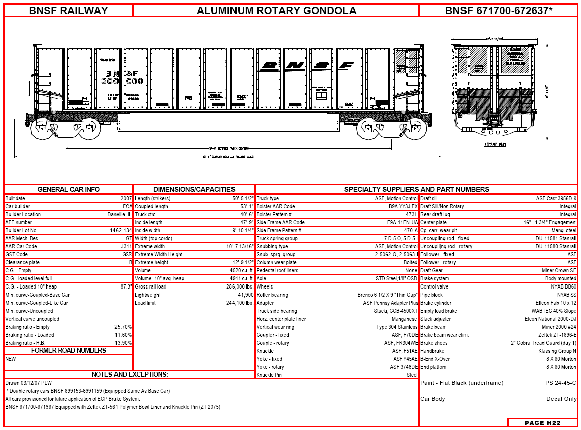
                      So as an example of setting brake shoe force, let's look at this BNSF Bethgon.

                      We can see at the bottom of the "GENERAL CAR INFO" column a braking ratio of 11.6% loaded, 25.7% empty, and 13.9% with the handbrake. Now it's important to understand what these braking ratios are saying. The loaded and hand braking ratios are given when the car is at gross rail load, which is 286,000 pounds, and the empty braking ratio is from the train brakes when empty, at the light weight of 41,900 pounds (these weights are listed at the bottom of the "DIMENSIONS/CAPACITIES" column). This document was drawn 2007, after the braking ratio was changed to be defined from 90 psi brake pipe pressure, so that loaded braking ratio is going to be measured around 65 psi brake cylinder pressure. However, the same won't be true for the empty braking ratio as this drawing also says this has a 40% empty load brake system (in the middle of the rightmost column). There can be quite a bit of variability in empty/load equipment, so that 40% system might not give exactly 26 psi brake cylinder pressure, and you'll probably never match the listed empty braking ratio perfectly.

                      In general, the loaded and handbrake ratios are most relevant. The brake force while empty should then be derived from the presence or lack of an empty/load system, as attempting to use the given empty braking ratio to calculate a force can cause all sorts of problems. So, let's focus entirely on that 11.6% of 286,000 for full service, and 13.9% of 286,000 for the handbrake.

                      286,000 lb * 0.116 = 33,176 lb (brake SHOE force at 65 psi)
                      286,000 lb * 0.139 = 39,754 lb (brake SHOE force at 100% handbrake)

                      Thus, in OR we enter: (note: MaxHandbrakeForce is measured as SHOE force when ORTSMaxBrakeShoeForce is used, otherwise it measures FRICTION force. There is NOT an "ORTSMaxHandbrakeShoeForce" parameter)
                      Code:
                          ORTSBrakeForceReferencePressure ( 65psi )
                          ORTSMaxBrakeShoeForce ( 33176lb )
                          MaxHandbrakeForce ( 39754lb )
                      Of course, that will be fine for the loaded car, but for the empty one we have to remember to add the load proportioning valve! Keep everything else the same though. The load proportioning valve will reduce the brake cylinder pressure, which will reduce the force, even though the values of ORTSMaxBrakeShoeForce and ORTSBrakeForceReferencePressure have not changed. Note that you might actually want to reduce MaxHandbrakeForce, as your virtual conductor (maybe your real conductor too, I don't know them) is not clever enough to use less handbrake on lighter cars, so you can happily get skidding if you don't reduce the handbrake force.
                      Code:
                          ORTSBrakeRelayValveRatio ( 0.4 )
                          ORTSBrakeRelayValveInshot ( -15psi )
                          ORTSBrakeRelayValveApplicationRate ( 10psi/s )
                          ORTSBrakeRelayValveReleaseRate ( 10psi/s )
                      
                          ORTSBrakeForceReferencePressure ( 65psi )
                          ORTSMaxBrakeShoeForce ( 33176lb )
                          MaxHandbrakeForce ( 39754lb )​
                      ​
                      Last edited by pschlik; 12-07-2025, 13:02.

                      Contributing to ORTS since 2023
                      Find me on GitHub @SteelFill

                      Like what I do? Join my Patreon to help me do more!

                      Comment

                      • pschlik
                        Senior Member


                        • Jun 2011
                        • 289
                        • Missouri
                        • MSOR

                        #12
                        Guessing Braking Ratios
                        While this approach is incredibly simple, just multiply two numbers a couple times, you will never find braking ratios for every train car you want to model. It takes time to measure them...time railroads aren't really interested in spending when it has no operational benefit and is not regulated. Luckily(?), braking ratios vary wildly between cars and over the lifetime of an individual car (unsurprisingly getting worse over time in most cases) so just about any braking ratio adjacently close to the AAR specification is reasonable. As with the real data, making a guess should start with a loaded braking ratio, then see what the empty braking ratio would be, verifying that is also within the specification (if it isn't, that usually means adjustments to the braking force or empty/load are needed).

                        As for "the specification", that has changed over time and even within a given specification there are different requirements for different types of freight cars, so what's reasonable for a given train car will depend on the type of rolling stock, the era the car was built in, and the era you are trying to represent. Old equipment might have been built to a different standard to the present one, might have deteriorated to be below the original spec, or been rebuilt to a newer standard. The exact choice depends on the specific car being depicted and the intended experience.

                        The current freight specification (introduced 1997, revised 2004) is as follows:
                        Braking ratios are all determined after a 30 psi reduction from 90 psi brake pipe pressure (usually 65 psi brake cylinder pressure). This standard is meant for high friction composite brake shoes only (more on brake shoes later). Keep in mind these requirements are the same regardless of the weight of the train car.
                        For any rebuilt intermodal equipment:
                        Gross Load Braking Ratio 11% to 13% | Empty Braking Ratio 15% to 38% | Gross Load Handbrake Braking Ratio Min 10%
                        For any rebuilt standard freight equipment:
                        Gross Load Braking Ratio 8.5% to 13% | Empty Braking Ratio 15% to 38% | Gross Load Handbrake Braking Ratio Min 10%
                        For any new freight equipment built after 2004 (before 2004, this extra requirement didn't exist):
                        Gross Load Braking Ratio 11% to 14% | Empty Braking Ratio 15% to 32% | Gross Load Handbrake Braking Ratio Min 10%

                        Unsurprisingly, new rolling stock is held to a higher standard than old rolling stock as we have gotten better at tuning brake systems and demands on braking systems have increased due to longer trains and heavier loads.


                        For routes in the past, the previous standard (applicable from 1964-1997, I think) will be more appropriate:
                        Braking ratios are all determined at 50 psi brake cylinder pressure, or whatever fraction of 50 psi would be present on cars with empty/load equipment. This standard covers both cast iron and high friction composite brake shoes as it was made right in the transition between the two.
                        Standard freight cars with cast iron brake shoes:
                        Gross Load Braking Ratio 13% to 20% | Empty Braking Ratio Max 53% | Gross Load Handbrake Braking Ratio Min 13%
                        Standard freight cars ​with high friction composite brake shoes:
                        Gross Load Braking Ratio 6.5% to 10% | Empty Braking Ratio Max 30% | Gross Load Handbrake Braking Ratio Min 11%
                        Freight cars with direct acting (leverless) brake cylinders and high friction composite brake shoes (such brake systems are not common):
                        Gross Load Braking Ratio 6.5% to 10% | Empty Braking Ratio Max 33% | Gross Load Handbrake Braking Ratio Min 11%
                        Cabooses with cast iron brake shoes (for both handbrakes and train brakes):
                        Empty Braking Ratio 35% to 45%
                        Cabooses with high friction composite brake shoes (for both handbrakes and train brakes):
                        Empty Braking Ratio 18% to 23%

                        Note that cast iron brake shoes require much higher braking ratios due to lower friction, and that the braking ratios for composite brake shoes are lower than the modern standard due to the lower brake cylinder pressure (the 6.5% to 10% range is actually exactly the same as the modern 8.5% to 13% range when accounting for the pressure difference).


                        Going back even further​​​ when cast iron brake shoes were standard (this spec is from the 1940s), the specification gets looser:
                        Braking ratios (this far back in history, you are likely to see the term "brake power", which is calculated the same as braking ratio, but typically uses the empty weight of the train car specifically) are determined at 50 psi brake cylinder pressure as usual. This is assumed to be with cast iron brake shoes as composite brake shoes had not been invented yet.
                        Standard freight cars:
                        Empty Braking Ratio 50% to 70% | Empty Handbrake Braking Ratio Min 60%​
                        Refrigerator cars (no, I do not know why refrigerator cars are special):
                        Empty Braking Ratio 50% to 60% | Empty Handbrake Braking Ratio Min 60%

                        Even further back, to the 1910s, I've seen some more variety of guidelines (I don't think this is an official spec, just advice):
                        Freight car empty braking ratio: Max 70%​ at 50 psi
                        Passenger car empty braking ratio: Max 90% at 60 psi
                        Steam tender empty braking ratio: Max 100% at 45 psi
                        Steam locomotive braking ratio: Max 75% at 45 psi

                        Old standards generally didn't specify loaded braking ratios, as the goal of the standard was to require car builders to design brake systems that wouldn't lock up the wheels regardless of load. Loaded braking ratio was less of a concern as most train cars weren't high enough capacity for brake performance to become awful when fully loaded. The goal should still be a loaded braking ratio above 15%, if that isn't possible while staying within the empty braking ratio standard then you probably have something with basic empty/load equipment, which would not function the same as the relay valve style covered in this thread. Older systems are less standard, so should be considered on a case by case basis.


                        Making Your Guess
                        Once the applicable specification has been found for the freight car with unknown braking performance, select (perhaps randomly) a braking ratio within the allowed range, or if there's just a min/max put it within 5% or so of the min or max. Consider also that the specs are generally only checked against newly deployed rolling stock. Something that's been out in the wild for a long time can fall out of spec and there's not any hard requirement to keep things in spec, as this is an industry standard and not a legal requirement. Wear on the brake rigging can reduce the effective lever ratio, making the brakes too weak on the loaded car. Rust on the car itself can reduce the empty weight, causing the empty braking ratio to increase too high. Sometimes both of these effects can happen simultaneously (fun!)​

                        Then, calculate a brake force from the selected braking ratio, and recalculate the braking ratio using that force when the train car is empty (if you started with a loaded braking ratio) or loaded (if you started with an empty braking ratio). If both loaded and empty braking ratios are within the allowed range simultaneously, you are good to go. If not, try adjusting the brake force used until both braking ratios are good. In some cases, you will end up below the minimum loaded braking ratio and above the maximum empty braking ratio at the same time. That means empty/load equipment of some sort will be needed, so try 60% empty/load and see if that can bring things in line, if that doesn't work try 50%, and so on. But, if possible, use empty/load such that the resulting braking ratios are in the middle of the allowed range. A freight car with a 9% loaded braking ratio and 35% empty braking ratio when using 60% empty/load might be in spec (for pre-2004 stuff), but it would be smarter to make that with an 11% loaded braking ratio and 40% empty/load to produce a more sensible 28.5% empty braking ratio (which is also in spec for post-2004).

                        Example Guess
                        As a practical example, I'll consider a 4 bay ACF covered hopper. I have spec sheets (including braking ratios) for 2 bay and 3 bay ACF hoppers, which can help me guess some details of the braking system, but not brake performance. To start, we need to have the loaded and empty weights, or else braking ratios are useless. Let's say for this one I see the stenciling says it's 263,000 pounds loaded and 72,000 pounds empty. As a 263k car, I know it's probably older than the latest braking standards, but it still is stenciled to say it has composite brake shoes so it's not ancient (263k equipment is too heavy to reasonably use cast iron brake shoes anyway). That means it's modern enough to still be around today, and let's say I'm using it on a modern route, so it makes sense to work off of the latest rules for rebuilt freight cars.

                        With the weight and relevant standard (1997) identified, a guess at a loaded braking ratio is needed. The standard calls for 8.5% to 13%, so let's randomly come up with a value in that range like 11.8%. And for the handbrake ratio, it should be at least 10%, but for a bit of spice let's randomly generate 10.6%.
                        ​
                        263,000 lb * 0.118 = 31,034 lb (ORTSMaxBrakeShoeForce)
                        263,000 lb * 0.106 = 27,878 lb (MaxHandbrakeForce)

                        Now since we started with a loaded braking ratio, we should check the empty braking ratio using the same brake force (start by assuming no empty/load unless it's clear that empty/load is present; 263k cars were regularly built without empty/load).

                        31,034 lb / 72,000 lb = 0.431 = 43.1%

                        Ah, well out of spec as the empty braking ratio should be 15% to 38%. This is where the estimation process gets more interesting, as we clearly can't get away with a totally random loaded braking ratio, even if it's in the allowed range. Because this is not a train car built after 2004, we can lower the loaded braking ratio to hopefully lower the empty braking ratio sufficiently, but if this car were built after 2004 it would definitely require empty/load equipment to be in spec. So, now that we know the empty braking ratio is the limiting factor, we can work in reverse to see the maximum brake force (at 38% empty braking ratio) that would be reasonable here.

                        72,000 lb * 0.380 = 27,360 lb (max brake shoe force to be in-spec empty)
                        27,360 lb / 263,000 lb = 0.104 = 10.4% (max loaded braking ratio to simultaneously be in-spec empty)

                        Unsurprisingly for a 263k car, empty/load is not needed (and in fact, wouldn't be equipped at all) for both the loaded and empty braking ratios to be in spec, and there's even some wiggle room. Now we shouldn't go with this brake force directly, as it's not random at all (it gives exactly 38% empty braking ratio), which isn't interesting or believable; manufacturers won't build their train cars to exactly hit the limit every time! And again, this is a train car from over 30 years ago, wear and tear will have weakened the braking force further.

                        So, let's re-bias the braking ratio used to something random, but less than 10.4%, like 9.3%, and recalculate to see if the empty braking ratio is less extreme.

                        263,000 lb * 0.093 = 24,459 lb
                        24,459 lb / 72,000 lb = 0.340 = 34.0% (pretty reasonable for a non empty/load 263k car)

                        Then, when plugging into OR, remember the ORTSBrakeForceReferencePressure. Because this example was done using the modern limits on braking ratio, the reference pressure for our braking ratios and the brake shoe force calculated from there is 65 psi brake cylinder pressure.
                        Code:
                            ORTSBrakeForceReferencePressure ( 65psi )
                            ORTSMaxBrakeShoeForce ( 24459lb )
                            MaxHandbrakeForce ( 27878lb )​
                        And there, we took a train car we didn't know much about (I didn't even share a photo, this train car is purely hypothetical) and generated brake shoe forces that are actually reasonable and based on real principles, even if the values are made up. This will give much more believable braking distances than throwing around numbers someone dreamt up from the MSTS days. This process can be generalized to all sorts of freight rolling stock, but it does get a bit more involved when empty/load shows up. If empty/load is used, remember to multiply the brake shoe force by the empty/load ratio before calculating the empty braking ratio, and to try multiple empty/load ratios to find what works well (just remember, 35% and 30% empty/load are not typical).​

                        Contributing to ORTS since 2023
                        Find me on GitHub @SteelFill

                        Like what I do? Join my Patreon to help me do more!

                        Comment

                        • pschlik
                          Senior Member


                          • Jun 2011
                          • 289
                          • Missouri
                          • MSOR

                          #13
                          Brake Shoes
                          So that is a lot about the normal force side of friction, but even then, we couldn't entirely escape the impact of the coefficient of friction. Because different brake shoe materials provide different coefficients of friction, different normal forces (braking ratios) are needed to get the same amount of deceleration. Brake shoe friction is actually much easier to set up in OR 1.6; ORTSBrakeShoeType takes a lot less information to set up compared to using ORTSBrakeShoeFriction (though either can still be used).

                          For our case here with American freight equipment, you are most likely to use ORTSBrakeShoeType ( Cast_Iron_P6 ) for older equipment and ORTSBrakeShoeType ( High_Friction_Composite ) for newer equipment. You'll note the post 1996 standards don't even mention cast iron brake shoes as it's assumed they aren't used at all by that time. Conversely, standards before 1960 won't mention composite brake shoes as those hadn't been invented yet. If you have a train car built between the 60s and 90s, it's still fairly trivial to tell when to use cast iron or composite brake shoes as everything using composite brake shoes will have stenciling saying as much (I'm sure many have seen the "2 IN HF COMP SHOES" stencil). Composite brake shoes are also the only viable option for high gross load equipment; the lower friction of cast iron brake shoes is entirely inadequate for 263K or heavier equipment.

                          OR also supports "high phos" cast iron brake shoes with ORTSBrakeShoeType ( Cast_Iron_P10 ). As far as I can tell, this style isn't so common in the US as, despite offering better performance than regular cast iron brake shoes, they were introduced in the 70s after composite brake shoes had already become preferred. Don't assume these are used on American rolling stock unless a spec sheet specifically says so. And there's also ORTSBrakeShoeType ( Disc_Pads ) for equipment with composite disc brakes but putting disc brakes on freight equipment is more of a British thing.

                          Note there are other brake shoe materials out there that are not considered by ORTSBrakeShoeType as the method used is pretty specific and follows one specific research report, which itself only considered the most common types of brake shoes. There is such a thing as low-friction and medium-friction composite brake shoes, usually used to replace cast iron brake shoes without increasing friction so much that wheel sliding occurs. Go back far enough in history and you might encounter wooden brake shoes. For such brake shoes, custom curves with ORTSBrakeShoeFriction would be required, but for a vast majority of rolling stock, the built in brake shoes are going to be fine.


                          Something special about the predefined brake shoes and the research report used as reference is that the coefficient of friction developed depends on more than just speed. However, this means it needs to know a bit more information about the train car. One of the impacts on the coefficient of friction is the amount of force applied per brake shoe. Note that all instances of ORTSMaxBrakeShoeForce let OR figure out the total brake shoe force. To get the per shoe force, the number of brake shoes has to be given with ORTSNumberCarBrakeShoes, assuming the shoe force is equally divided between all brake shoes (for well-designed brake rigging, this will be the case).

                          OR will guess that each wheel has 2 brake shoes, but this is not standard for US freight car designs which usually only use one brake shoe per wheel, so ORTSNumberCarBrakeShoes​ ( 8 ) will be typical.
                          Code:
                              ORTSBrakeShoeType ( High_Friction_Composite )
                              ORTSNumberCarBrakeShoes ( 8 )​​
                          ​

                          With detailed enough photos or models, it shouldn't be hard to tell when something has 1 or 2 brake shoes per wheel. This is only a challenge for systems with disc brakes as lots of disc brake systems use less predictable numbers of brake pads, which are also easier to place in locations that are hard to spot. Better documentation or photos from unusual angles may be needed to get the correct count in those cases. And for equipment with both tread brakes and disc brakes, set the number of brake shoes to the number of brake pads plus brake shoes.


                          We can now go a bit further now and combine all that's been covered with the info in that bethgon sheet and assemble the complete braking system for the train car. It has the DB-60 control valve, a bog standard 10 inch diameter brake cylinder (which uses the standard AB reservoir), 40% empty/load equipment on the empty car, and COBRA (high friction composite) brake shoes (which we can safely assume there's 1 of per wheel) giving us these settings:
                          Code:
                              BrakeSystemType ( "Air_single_pipe" )
                              BrakeEquipmentType ( "Handbrake, Triple_valve, Auxiliary_reservoir, Emergency_brake_reservoir, Retainer_3_Position" )
                          
                              MaxApplicationRate ( 6psi/s )
                              MaxReleaseRate ( 2.5psi/s )
                              
                              ORTSBrakeInsensitivity ( 3psi/min )
                              ORTSInitialApplicationThreshold ( 1.5psi )
                          
                              ORTSEmergencyResQuickRelease ( 1 )
                          
                              ORTSUniformChargingThreshold ( 3psi )
                              ORTSUniformChargingRatio ( 2 )​
                          
                              ORTSQuickServiceLimit ( 10psi )
                              ORTSQuickServiceApplicationRate ( 15psi/s )
                              ORTSQuickServiceVentRate ( 2.5psi/s )​​
                          
                              ORTSAcceleratedApplicationFactor ( 1.75 )
                              ORTSAcceleratedApplicationMaxVentRate ( 3psi/s )​
                          
                              ORTSEmergencyValveActuationRate ( 20psi/s )
                              ORTSEmergencyDumpValveRate ( 80psi/s )
                              ORTSEmergencyDumpValveTimer ( 120s )​​
                          
                          
                              EmergencyResCapacity ( 3500in^3 )
                              ORTSAuxiliaryResCapacity ( 2500in^3 )
                              
                              MaxAuxilaryChargingRate ( 1.05psi/s )
                              EmergencyResChargingRate ( 1.0psi/s )
                              ORTSMainResPipeAuxResCharging ( 0 )
                          
                          
                              Comment ( Commenting out the load proportioning valve on the loaded train car.
                              ORTSBrakeRelayValveRatio ( 0.4 )
                              ORTSBrakeRelayValveInshot ( -15psi )
                              ORTSBrakeRelayValveApplicationRate ( 10psi/s )
                              ORTSBrakeRelayValveReleaseRate ( 10psi/s )​
                              )​
                          
                          
                              ORTSBrakeCylinderDiameter ( 10in )
                              ORTSBrakeCylinderPistonTravel ( 7.5in )
                              ORTSNumberBrakeCylinders ( 1 )
                              
                              ORTSBrakeCylinderPipingVolume ( 190in^3 )
                              
                              ORTSCylinderSpringPressure ( 5psi )​
                          
                          
                              ORTSBrakeShoeType ( High_Friction_Composite )
                              ORTSNumberCarBrakeShoes ( 8 )​
                          
                              ORTSBrakeForceReferencePressure ( 65psi )
                              ORTSMaxBrakeShoeForce ( 33176lb )
                              MaxHandbrakeForce ( 39754lb )​​​​​
                          Obviously that gets a bit messy, I use include files for this reason (lots of train cars use the DB-60, it's easier to say "include DB-60 control valve" than to copy paste it every single time!) Hopefully it's quite clear how this can be expanded​ to a whole fleet of freight equipment to give reasonable brake response that varies in sensible ways. With different types of brake equipment, changing the makeup of a train can change the brake response in subtle ways that people have to adapt to. That, and with reasonable brake settings you should be able to avoid making brakes that feel like anchors or end up being entirely inadequate for that one steep section of a route, as has happened in the past when creators throw around brake numbers willy nilly. Hopefully the next generation of trains will give a more sensible driving experience.​

                          Contributing to ORTS since 2023
                          Find me on GitHub @SteelFill

                          Like what I do? Join my Patreon to help me do more!

                          Comment

                          Working...