Possible for Load to Span Two Cars and Pivot Properly?

Collapse
X
 
  • Time
  • Show
Clear All
new posts
  • PerryPlatypus
    Senior Member

    • Jun 2009
    • 951
    • Spokane, WA
    • English
    • MSOR

    #1

    Possible for Load to Span Two Cars and Pivot Properly?

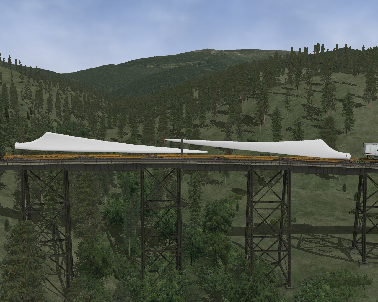
    Question for those with experience doing complex / articulated car or locomotive shapes... Is there any way to have a car with a load where one end is fixed on one end of a flatcar, and the other end is fixed on a point on a separate flatcar (or at least having the other end follow the centerline of the track?) In other words, a load that is supported by two separate cars and rotates properly in curves? Doesn't need to look perfect, but close-ish

    The below screenshot hopefully helps explain what I am trying to aim for. I'd like to be able to have the intermediate mount for supporting this wind blade located where I drew the red oval, and thus the "centerline" of the wind blade would be on the red line (as opposed to be fixed to the same angle of the lefthand flatcar, like it currently is).

    Wind Blade by Sean Kelly, on Flickr
    ~Sean Kelly~
    SP Shasta Route for Open Rails: https://www.trainsimulations.net/sp-shasta​
    MRL Mullan Pass for Open Rails: https://www.trainsimulations.net/mullanpass
  • charland
    3000 Post Veteran


    • Dec 2006
    • 3107
    • Brockville, ON, CA
    • General

    #2
    Here's a theory for you. You can make a car with three trucks, so if the two cars were made in the same file, and the load had two pivot point and the points about the center of the two cars was named Wheels31 and the other end Wheels 32, would that not do the trick?

    Paul :-)

    Comment

    • eolesen
      9500 Post Veteran and Administrator


      • Dec 2002
      • 9583
      • NS MP245.4 CNO&TP South District
      • English, SQL
      • General

      #3
      Yep, that's what I was thinking. The blade essentially becomes part of the frame shape and not a load or FA.
      If you like what you see here at Trainsim.com, be it the discussions and knowledge in the forums, or items available in our library, I hope you'll consider a paid membership to help support keeping the site operating.... Thanks!

      Comment

      • geepster775
        2500 Post Veteran


        • Sep 2006
        • 2846
        • .
        • General

        #4
        If the blade carrier was made from a repurposed 48 ft spine car, carrying 2 blades per 5-unit car, end platforms A and B and center D platform would have load contact points. Middle platforms C and E would act like extended length drawbars that don't make contact with the load. Each blade load would generally follow the orientation of the middle drawbar units, except it would slide 'overboard' on tighter curves.
        My Open Rails videos https://www.youtube.com/@lakecities3663/videos

        Comment

        • charland
          3000 Post Veteran


          • Dec 2006
          • 3107
          • Brockville, ON, CA
          • General

          #5
          Up here in Canader they normally use two 85 foot flats per pair or blades. That would eliminate the need for any idler cars. That said, would idler cars not be the same as the setup for an articulated engine where the second engine is coupled to the first but the first still has couplers on each end.

          Paul :-)

          Comment

          • geepster775
            2500 Post Veteran


            • Sep 2006
            • 2846
            • .
            • General

            #6
            Most 5 unit spines are set up with trucks on both ends of the A, B and D platforms. The middle C and E platforms have no trucks or wheels. Could you somehow animate the blade load to shift from the centerline of the two truckless platforms (on straights) to overboard on the inward side on curves based upon some calculations taken from the degree of curvature experienced by the adjacent platforms? OR does track individual curvature encountered by each car.
            My Open Rails videos https://www.youtube.com/@lakecities3663/videos

            Comment

            • PerryPlatypus
              Senior Member

              • Jun 2009
              • 951
              • Spokane, WA
              • English
              • MSOR

              #7
              Originally posted by charland
              Here's a theory for you. You can make a car with three trucks, so if the two cars were made in the same file, and the load had two pivot point and the points about the center of the two cars was named Wheels31 and the other end Wheels 32, would that not do the trick?

              Paul :-)
              Trying to get a grasp of this and test in-game, and no luck so far, but I want to make sure I understand some things...

              To my knowledge, OR can only handle two Bogies, no more. I have tried a couple different setups trying to get past that, but none have succeeded. Anything above Bogie2 just acts like a rigid part of the frame.

              I'm not sure what you mean by naming the "points about the center of the two cars". Naming any object a wheel should make it rotate like a wheel if OR recognizes it as a wheel (although I'm not convinced Wheels 31 and 32 would even function since again, OR does not seem to recognize more than 2 bogies).

              I have even attempted to have the blade itself named Bogie3, but that does not seem to do anything, it is still locked to the orientation of one particular car rather than rotating as a separate object.

              Maybe I am missing something in hierarchy structure here... any specific help would be appreciated! Without the ability to handle more than 2 bogies, the idea of the 5-car articulated sets where there is an entire car between the two blade supports seems like a dream out of reach when I can't get even the 2-car setup to work properly.
              ~Sean Kelly~
              SP Shasta Route for Open Rails: https://www.trainsimulations.net/sp-shasta​
              MRL Mullan Pass for Open Rails: https://www.trainsimulations.net/mullanpass

              Comment

              • charland
                3000 Post Veteran


                • Dec 2006
                • 3107
                • Brockville, ON, CA
                • General

                #8
                I'm still using the full version of TS Modeler. When I open Train Part Names Bodie 1, 2 and 3 are there. Each Bogie has the option of up to three Wheels. I've not tried this before but I think that might be the only route for getting the blade to bridge the cars.

                Thinking about this now I'm wondering if the load needs couplers at each end and the end cars have one coupler at the center (or where the load pivot point is).

                I think all this goes back to an articulated engine where one set of drivers is an engine coupled under the rest of the engine and that engine still has end couplers as well.

                Just a theory right now.

                Paul :-)

                Comment

                • PerryPlatypus
                  Senior Member

                  • Jun 2009
                  • 951
                  • Spokane, WA
                  • English
                  • MSOR

                  #9
                  Hi Paul,

                  Thanks, what you describe is what I feared. I found multiple posts mentioning how TSM gives an option for a 3rd bogie, but that it does not actually function correctly (neither MSTS nor OR has the code to properly handle a 3rd bogie that actually rotates in alignment with the track and/or translates horizontally to stay on the rails in tight curves).

                  As I got deeper into the weeds, I realized that only a 3rd bogie really wouldn't work for me anyways, as it would cause the center of the blade to be positioned over track centerline in curves, leaving the two ends of the blade overhanging on the outside of the curve.

                  I am now of the belief that I simply cannot model what I am attempting without a major overhaul of the way OR handles things that actually adds functionality WELL BEYOND what MSTS was capable of (which is probably why it hasn't been done before!) On much shorter cars, like the schnabel cars in the file library, the "overhang" (deviation from centerline for one end of a load that extends beyond the length of the car shape it is mounted on) that happens on these types of cars is short enough that it is not a big visual drawback, but with these massive windblades on nearly 90 foot long flatcars, (or 3 spine cars as Geepster mentioned), it's VERY noticeable in curves.

                  I'll make a few last attempts, but it seems like without someone adding the OR code for more than 2 fully functioning bogies plus some other abilities like being able to have a second "frame" type object that is on two "fake bogies" (in this case the fake bogies would be the two supports holding the wind blade) and this second "frame" object can rotate independently of the frames of the railcars... (and the ability to almost have "bogies within bogies" in terms of shape hierarchy) then I am dead in the water with this.
                  Last edited by PerryPlatypus; 05-18-2021, 10:51.
                  ~Sean Kelly~
                  SP Shasta Route for Open Rails: https://www.trainsimulations.net/sp-shasta​
                  MRL Mullan Pass for Open Rails: https://www.trainsimulations.net/mullanpass

                  Comment

                  • charland
                    3000 Post Veteran


                    • Dec 2006
                    • 3107
                    • Brockville, ON, CA
                    • General

                    #10
                    Hi Sean,

                    I think you CAN do this.

                    If you can make a center section of a five unit spine flat that has no trucks, then you can make a set of blades that have no trucks and is sitting at eight feet above the rails. The center sections of the spine car have couplers even though they have no trucks, the blades would have couplers too. The one thing you would need to do is to give the two end flats a third coupler near the center of the car to couple the blades to. The car would still have both normal end couplers to add the idler cars between the ends.

                    This theory is based on however a Bigboy gets put together in Activity Editor so the second engine is coupled underneath the rest of the model, but if they can do that, then your blades should be able to be coupled in Activity Editor as well.

                    Paul :-)

                    Comment

                    • rowie
                      Senior Member
                      • Dec 2004
                      • 186
                      • QLD, Australia.

                      #11
                      Try making the blade an individual car with a wheel at each location you want it to pivot, and make the coupling length very short in the .wag file. I did that to the centre trailers of my TTEX cars. Without the wheels, the trailer would just pivot around it's axis. With the wheels, they follow the track centre line, which made the trailer pivot on the hitch like the prototype.

                      It won't be perfect for your situation. The blade end won't stay in the centre of the car, due to the wheels following the track centreline. But certainly better than what it is doing now.

                      ttex1.jpg

                      ttex2.jpg

                      ttex3.jpg

                      The bogies and wheels are alpha removed. Changed the texture so they are visible. The mid trailer length is 0.29m and you might have to offset the flatcars slightly to make up for the additional length.

                      Search the file library for TTEX.

                      Have fun

                      Comment

                      • PerryPlatypus
                        Senior Member

                        • Jun 2009
                        • 951
                        • Spokane, WA
                        • English
                        • MSOR

                        #12
                        Thanks much Rowie, your model gave me some inspiration for sure!

                        The one missing puzzle piece I was running into was the fact that the midpoint of my windmill load was not centered between two cars, making it a bit harder. After a lot of trial and error, followed at last by doing some fun algebra, I figured out how to use the r0 values in the coupler fields to piece this together (using large negative r0 values to move the "coupler" for the start and end of the windmill blade). Turns out a 5-car articulated spine set with two blades IS POSSIBLE! As you noted Rowie, the location of the common support is not absolutely perfect because it follows track centerline rather than the centerline of the car, but it is close enough for normal degrees of curvature. Still some fiddling to go, but some screenshots below! (I think using something similar to this, it may finally be possible to have 3 or 4 truck locomotives with middle trucks that follow the rails in tight curves).

                        Thanks one and all for suffering through this with me

                        Open Rails 2021-05-19 05-49-13 by Sean Kelly, on Flickr

                        Open Rails 2021-05-19 05-55-26 by Sean Kelly, on Flickr

                        Open Rails 2021-05-19 05-55-36 by Sean Kelly, on Flickr
                        Last edited by PerryPlatypus; 05-19-2021, 19:27.
                        ~Sean Kelly~
                        SP Shasta Route for Open Rails: https://www.trainsimulations.net/sp-shasta​
                        MRL Mullan Pass for Open Rails: https://www.trainsimulations.net/mullanpass

                        Comment

                        • rowie
                          Senior Member
                          • Dec 2004
                          • 186
                          • QLD, Australia.

                          #13
                          Looks like you got it sorted out Where are the blades coupled in the consist? I forgot to say adding the wheels stopped the centre trailer from shaking badly, due to the short coupled length. Like some of the EOT devices shake when the camera is focused on them.

                          Comment

                          • conductorchris
                            2500 Post Veteran

                            • Mar 2010
                            • 2905
                            • Vermont
                            • General

                            #14
                            That now looks pretty cool. Want!
                            Christopher

                            Comment

                            Working...